
Chemical Industry
PVC, PE, PP, fertilizers, sodium carbonate, dyes, pesticide granules, inorganic salts and organic crystals.
Product Overview
Conductive and convective heat transfer for continuous drying with reduced process-air demand. Designed and manufactured for loose materials suitable for continuous internal-heating fluid-bed drying across chemical, pharmaceutical, food and environmental applications. Review the working principle, performance features and available configuration details below when specifying your industrial project.
Product Essentials
Select a topic from the directory. The content stays in one focused workspace for faster comparison.
Interactive Equipment View
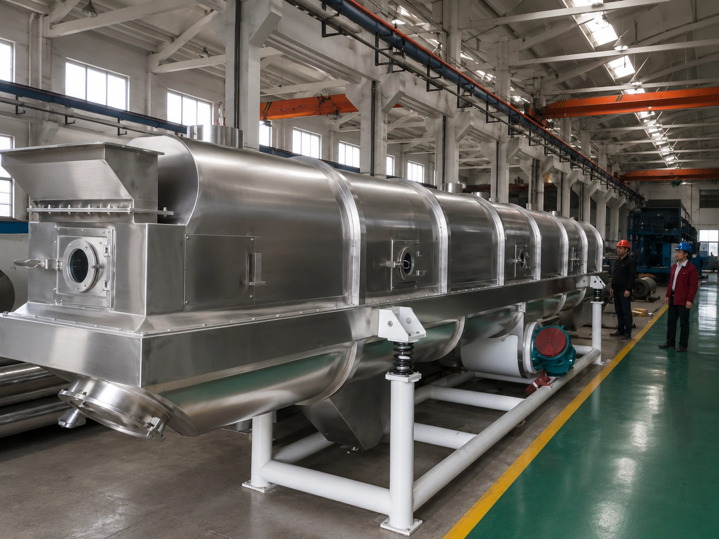
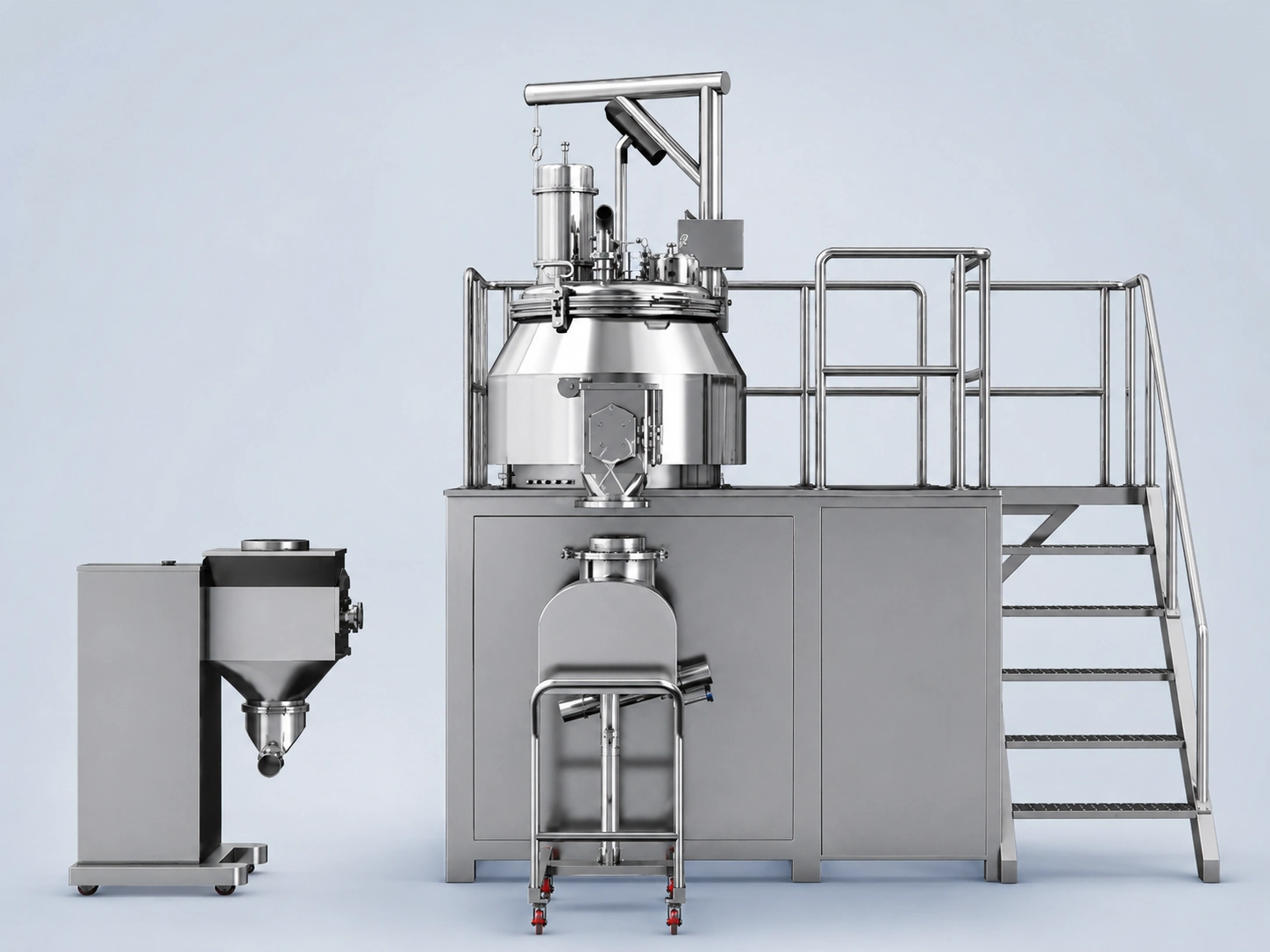
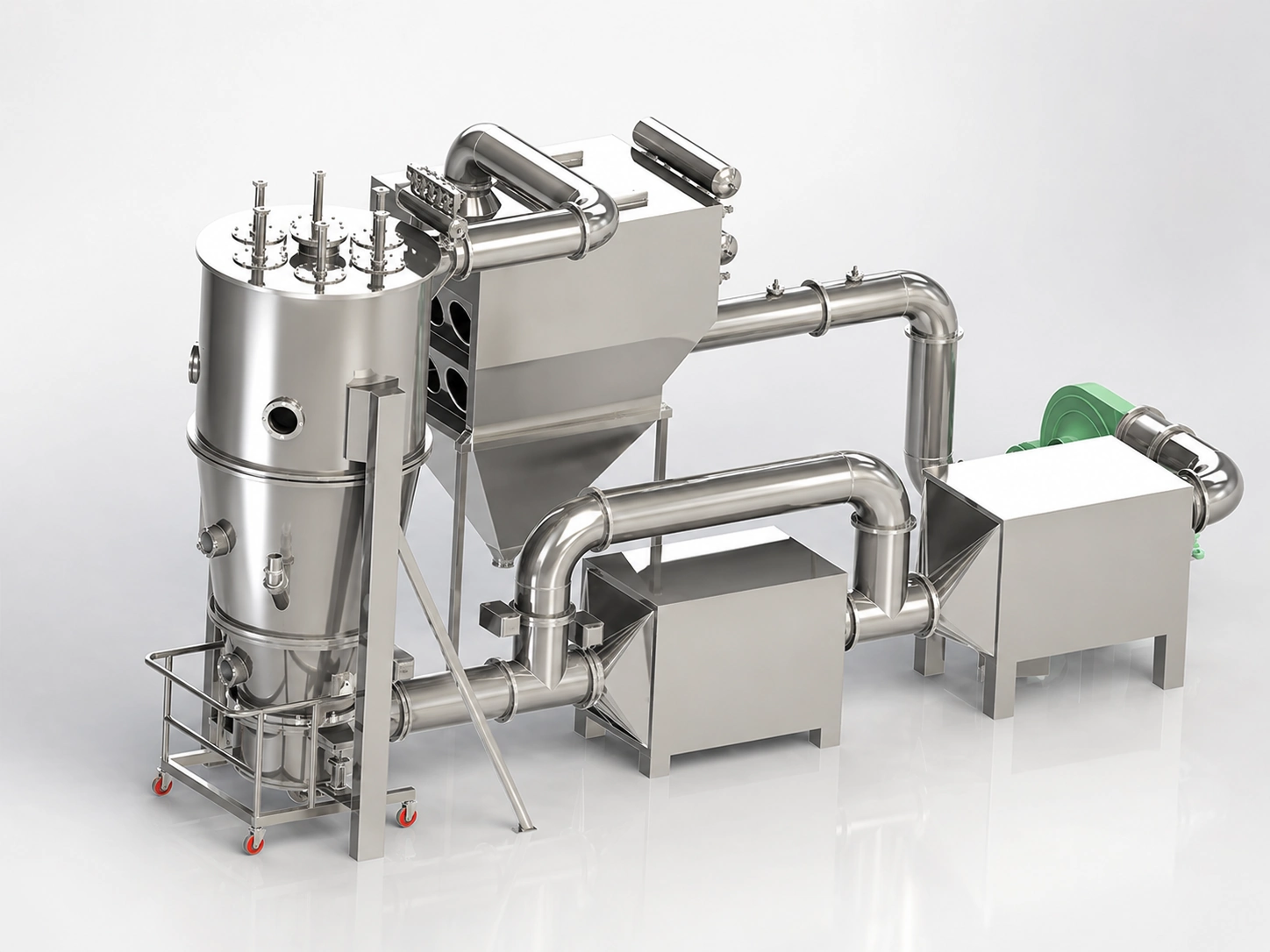
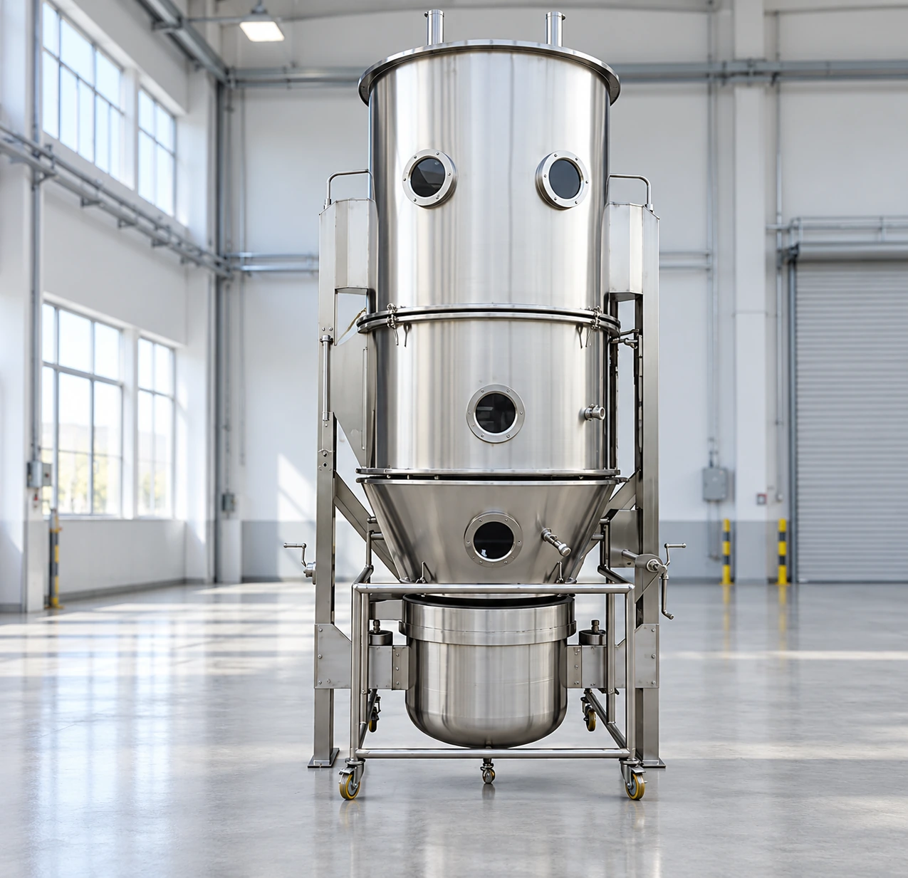
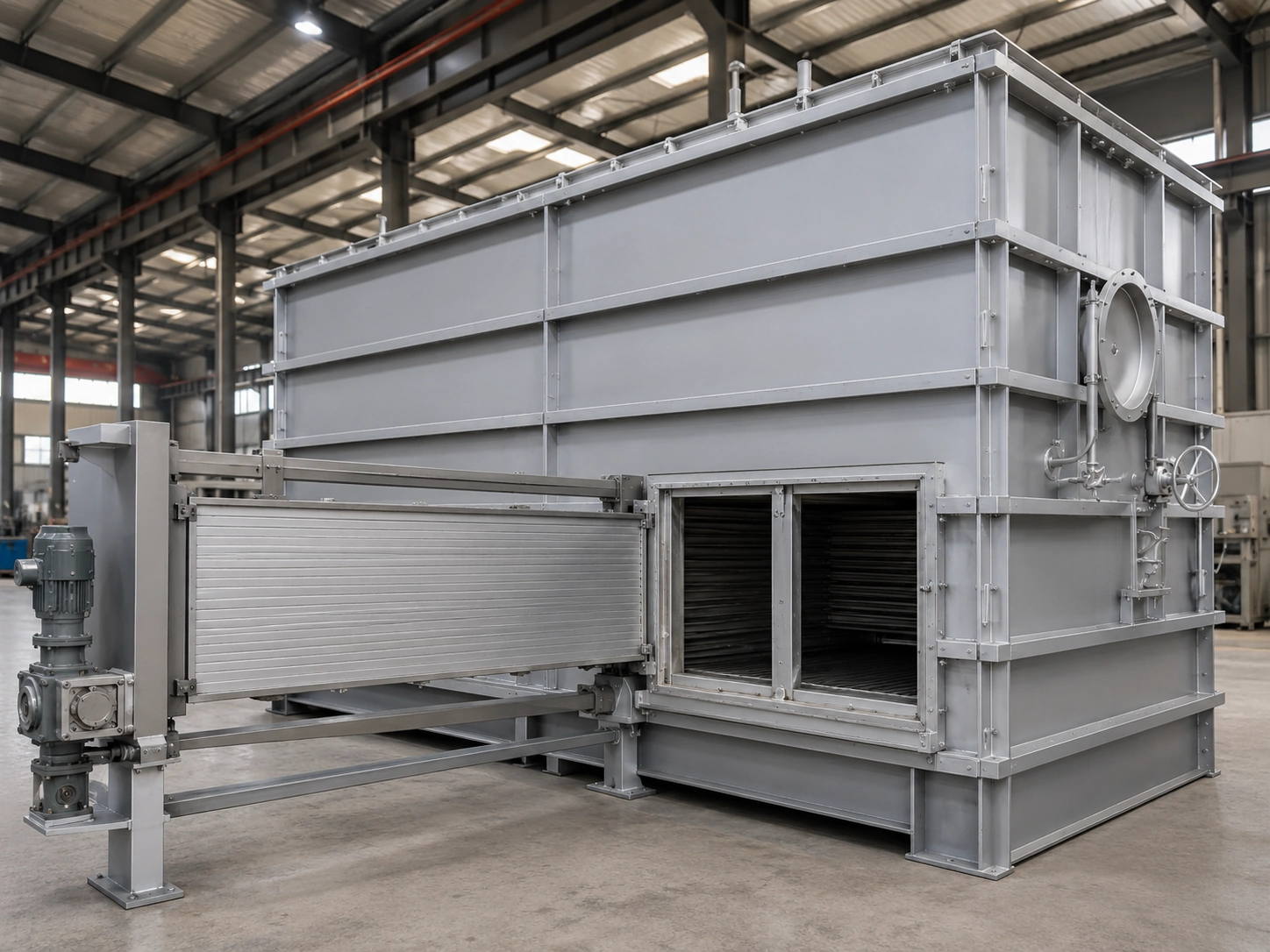
Drag the 3D model to rotate and use the equipment photographs for a quick real-world reference.
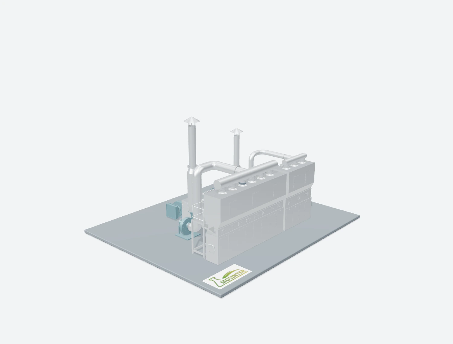
Interactive preview unavailable. Please contact us for equipment details.
Drag to rotate · Scroll or pinch to zoom
Applications
Applications include loose materials suitable for continuous internal-heating fluid-bed drying across chemical, pharmaceutical, food and environmental applications. Confirm material properties and process conditions before selecting the equipment configuration.
PVC, PE, PP, fertilizers, sodium carbonate, dyes, pesticide granules, inorganic salts and organic crystals.
Antibiotic materials, pharmaceutical granules, traditional Chinese medicine extracts and enzyme preparations.
Sugar, monosodium glutamate, salt, soy protein, starch, feed additives, and fruit or vegetable granules.
Sludge granules and biomass particles where the material and process conditions permit fluidized drying.
Granular, powder, crystalline and fibrous materials.
Working Principle
Internal exchangers add a conductive heat-transfer path inside the material layer, while fluidizing air maintains movement and carries evaporated moisture from the dryer.
Heated air enters the lower chamber and passes through the distribution plate, bringing the wet material into a continuously moving fluidized state.
A heat-transfer medium circulates through immersed tubular exchangers and transfers heat to the surrounding material. The medium and utility conditions require confirmation for the selected configuration.
Fluidizing air supplies supplementary heat and removes moisture. Internal heating allows the required air volume to be reduced.
Dried material is discharged continuously after reaching the target moisture, while moist exhaust air passes through the selected dust-separation system.
Key Advantages
Actual performance depends on material characteristics, heating conditions, airflow and the selected equipment configuration.
Direct heat transfer inside the material layer reduces dependence on large volumes of hot air and supports higher thermal utilization.
Lower drying-air demand can reduce fan power and the load on downstream exhaust-treatment equipment.
Controlled internal heating helps maintain stable material temperature and reduce local overheating dryer.
Combined internal heat transfer and fluidization provide intensive heat and mass transfer within a compact processing section.
Heating-medium temperature and flow, fluidizing airflow and material residence time can be adjusted around the drying duty.
The internal exchanger and its contact material can be selected according to capacity, material characteristics and corrosion requirements.
Reduced exhaust airflow can decrease discharged heat loss and dust-treatment demand.
Technical Specifications
Listed values apply to the identified configuration. Confirm material conditions, utilities and optional equipment before selection.
| Parameter | Specification |
|---|---|
| Equipment Type | Internal Heating Fluid Bed Dryer |
| Drying Principle | Conductive + Convective Heat Transfer |
| Operation Mode | Continuous Drying |
| Control System | Conventional Control / PLC Touch Screen |
| Evaporation and moisture targets | To be confirmed according to configuration |
| Model | Fluid Area (m²) | Installed Power (kW) | Steam Pressure (MPa) | Steam Consumption (kg/h) | Inlet Air Temperature (°C) | Dimensions (mm) |
|---|---|---|---|---|---|---|
| Model 1 | 2.0 | 50 | 0.2–1.0 | 400–1000 | 100–300 | 3000×1300×4500 |
| Model 2 | 2.5 | 65 | 0.2–1.0 | 600–1200 | 100–300 | 3500×1300×4500 |
| Model 3 | 3.0 | 85 | 0.2–1.0 | 1400–2200 | 100–300 | 3600×1400×4500 |
| Model 4 | 3.5 | 95 | 0.2–1.0 | 1000–2000 | 100–300 | 4000×1500×4500 |
| Model 5 | 4.0 | 110 | 0.2–1.0 | 1200–2000 | 100–300 | 4600×1600×5000 |
| Model 6 | 5.5 | 130 | 0.2–1.0 | 1400–2200 | 100–300 | 5000×1650×5000 |
| Model 7 | 6.0 | 140 | 0.2–1.0 | 1600–2800 | 100–300 | 6000×1700×5000 |
| Model 8 | 7.0 | 165 | 0.2–1.0 | 1800–3200 | 100–300 | 6600×1750×5000 |
| Model 9 | 8.0 | 170 | 0.2–1.0 | 2000–2800 | 100–300 | 7500×1800×5000 |
| Model 10 | 10 | 210 | 0.2–1.0 | 2400–3600 | 100–300 | 10000×1850×6000 |
| Model 11 | 15 | 300 | 0.2–1.0 | 3200–4400 | 100–300 | 15000×1900×6500 |
| Model 12 | 20 | 320 | 0.2–1.0 | 4000–6000 | 100–300 | 20000×2000×7000 |
*Actual performance depends on material characteristics, production capacity, heating conditions and process requirements.
Selection Support
Provide the following process, utility and material data for preliminary model and configuration evaluation.
The appropriate dryer configuration is selected according to material characteristics and process requirements.