
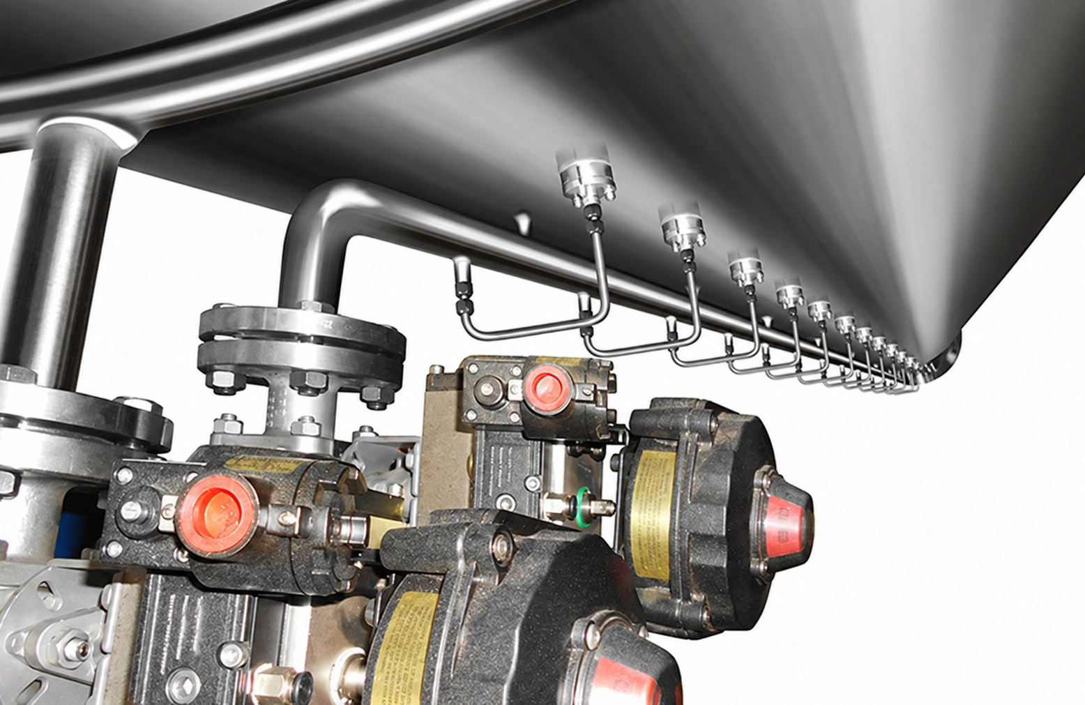
CIP cleaning option
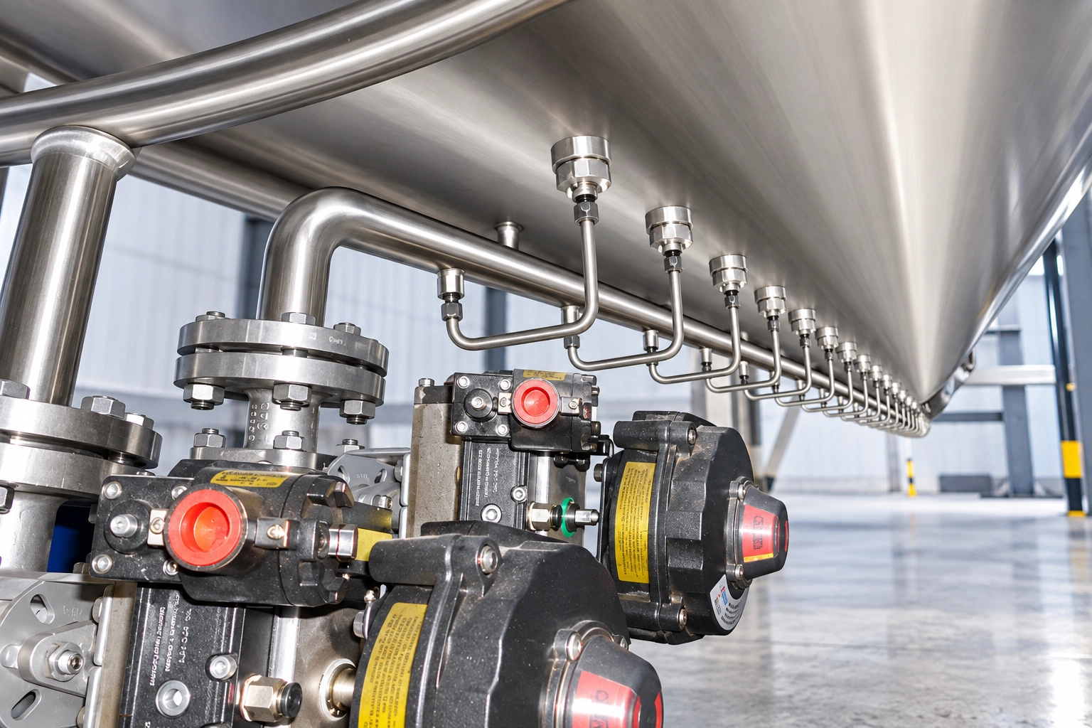
Internal sprays assist cleaning of contact surfaces. The cleaning procedure is selected for the material residue.
Industrial Mixers
The equipment combines a vertical ribbon agitator with high-speed side cutters to blend fine powders and fluid or semi-fluid materials while dispersing agglomerates with low energy demand and limited particle damage. Designed and manufactured for fine-powder blending and granular additions. Review the working principle, performance features and available configuration details below when specifying your industrial project.
Product Essentials
Select a topic from the directory. The content stays in one focused workspace for faster comparison.
Product Overview
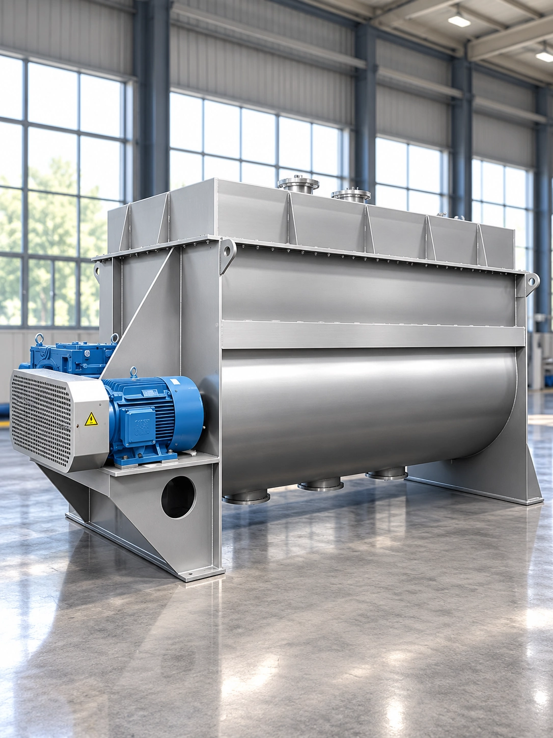
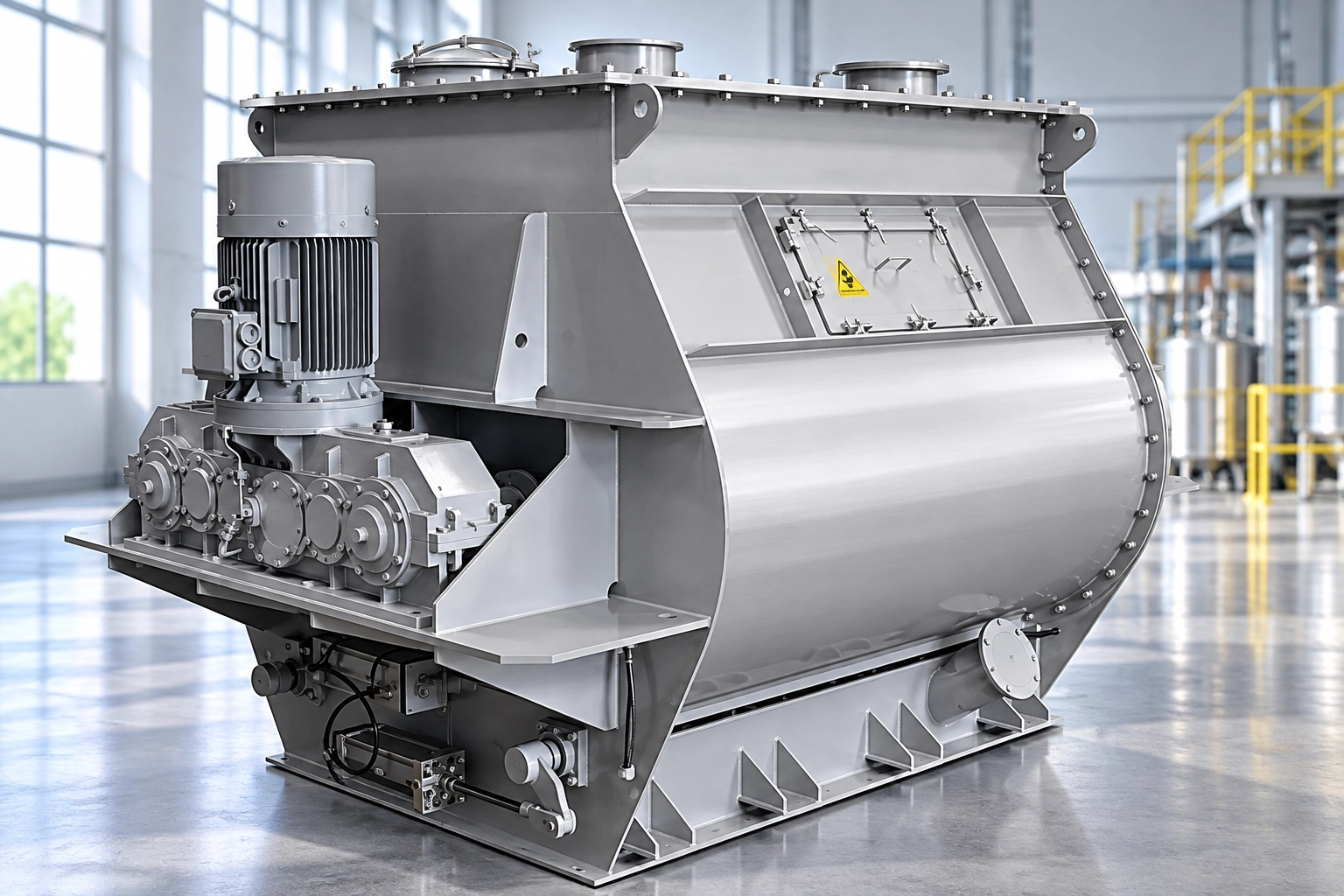
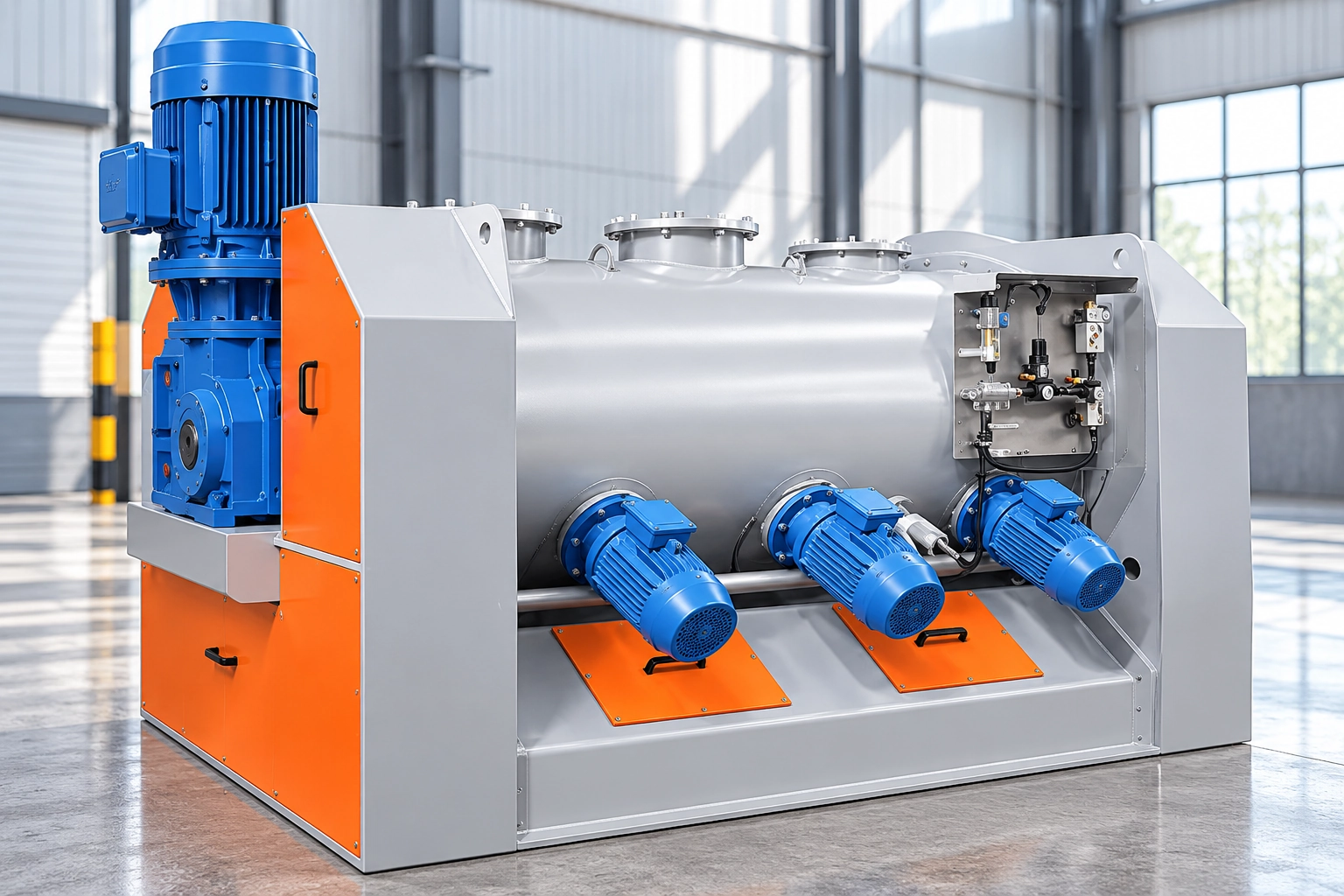
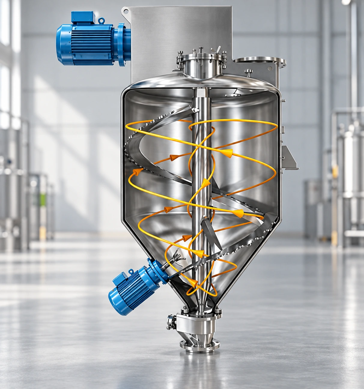
The mixer consists principally of a vertical mixing chamber, a central ribbon agitator and side-mounted high-speed cutters. The ribbon performs the main mixing duty while the cutters break up and disperse agglomerated or caked material.
This combined action provides uniform blending of particularly fine powders, granular additions, and fluid or semi-fluid materials such as paint formulations. The design delivers efficient circulation with low energy demand and limited particle damage.
Pressure, vacuum blending, reaction and bonding duties can be engineered as required. Optional systems include hollow-shaft liquid spraying, CIP cleaning and a vessel jacket for heating or cooling.
Typical Technical Data
Listed values apply to the identified configuration. Confirm material conditions, utilities and optional equipment before selection.
| Parameter | Reference value |
|---|---|
| Equipment type | High-efficiency vertical ribbon mixer |
| Series batch-capacity range | 20–15,000 kg |
| Series motor-power range | 1.1–55 kW |
| Primary agitator | Vertical ribbon |
| Auxiliary dispersion device | High-speed side cutters |
| Suitable feed forms | Fine powder / granular addition / fluid or semi-fluid material |
| Standard discharge concept | Pneumatic bottom outlet |
| Optional liquid addition | Hollow-shaft spray pipe with rotating atomizing nozzle |
| Optional process modes | Pressure / vacuum blending / reaction / bonding |
| Optional cleaning | CIP system |
| Optional temperature control | Jacket heating or cooling |
Final equipment dimensions, utilities and performance must be confirmed before quotation.
Technical Specifications
Fifteen sizes cover 0.05–25 m³ nominal volume. Batch capacity depends on bulk density, working fill and material behavior.
| Reference Model | Nominal Volume (m³) | Batch Capacity (kg/batch) | Installed Motor Power (kW) | Equipment Weight (kg) |
|---|---|---|---|---|
| GPH-0.05 | 0.05 | 20–30 | 1.1 | 180 |
| GPH-0.1 | 0.1 | 40–80 | 1.5 | 280 |
| GPH-0.3 | 0.3 | 120–180 | 2.2 | 490 |
| GPH-0.5 | 0.5 | 200–300 | 4 | 550 |
| GPH-1 | 1 | 400–800 | 7.5 | 1100 |
| GPH-2 | 2 | 800–1200 | 11 | 1300 |
| GPH-3 | 3 | 1200–1800 | 15 | 1800 |
| GPH-4 | 4 | 1800–2400 | 18.5 | 2600 |
| GPH-6 | 6 | 2400–3600 | 18.5 | 2850 |
| GPH-8 | 8 | 3200–4800 | 22 | 3700 |
| GPH-10 | 10 | 4000–6000 | 30 | 4500 |
| GPH-12 | 12 | 4800–7200 | 37 | 5000 |
| GPH-15 | 15 | 6000–9000 | 45 | 5900 |
| GPH-20 | 20 | 8000–12000 | 45 | 6800 |
| GPH-25 | 25 | 10000–15000 | 55 | 7100 |
Reference values are for preliminary model comparison. Final batch capacity, drive power and weight must be confirmed for the selected material and options.
Optional functions are selected for material properties, cleaning requirements and temperature control.
Internal sprays assist cleaning of contact surfaces. The cleaning procedure is selected for the material residue.
Water cooling or steam/thermal-oil heating jackets can be specified for the process.
Applications
Applications include fine-powder blending and granular additions. Confirm material properties and process conditions before selecting the equipment configuration.
Uniform mixing of particularly fine powders and multicomponent dry formulations.
Distribution of granular ingredients within a fine-powder or mixed-material batch.
Mixing duties involving fine powders, paint-type materials and other flowable or semi-flowable products.
Cutter-assisted breakup and dispersion of caked or agglomerated feed.
Configured blending under positive pressure or vacuum where required by the process.
Engineered mixing for processes that include reaction or bonding operations.
Working Principle
The process route is selected around the material and product targets.
Fine powders, granular additions, or fluid and semi-fluid formulations enter the mixing chamber through the top feed port.
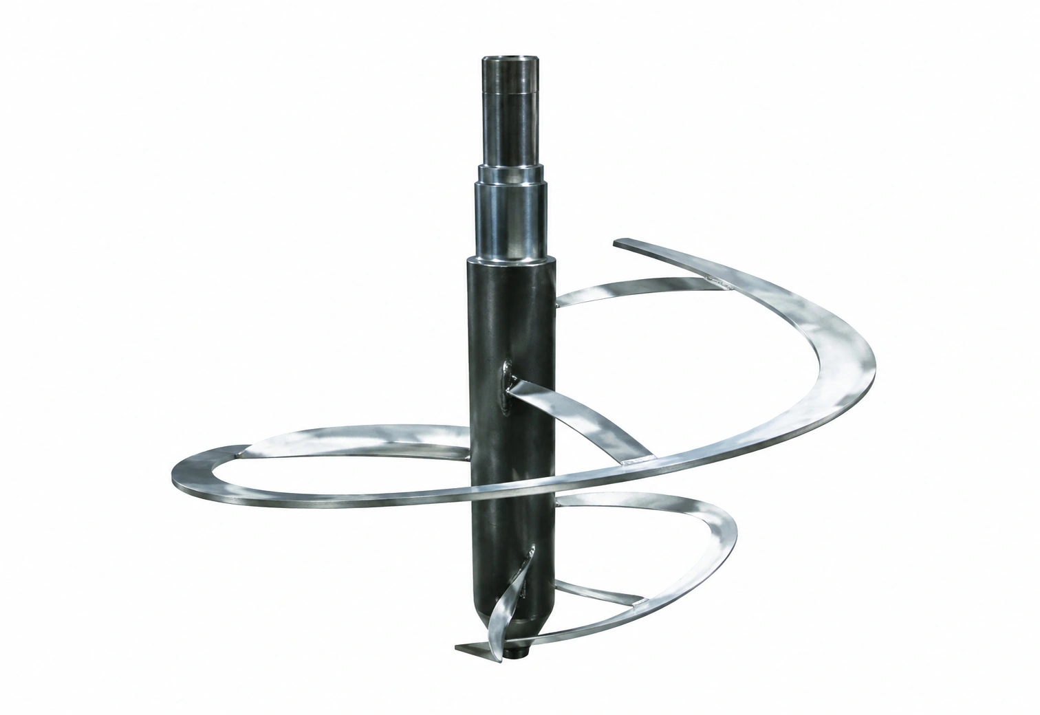
The vertical ribbon continuously lifts and circulates the material through the chamber.
Side-mounted cutters break up agglomerates and caked material while assisting distribution.
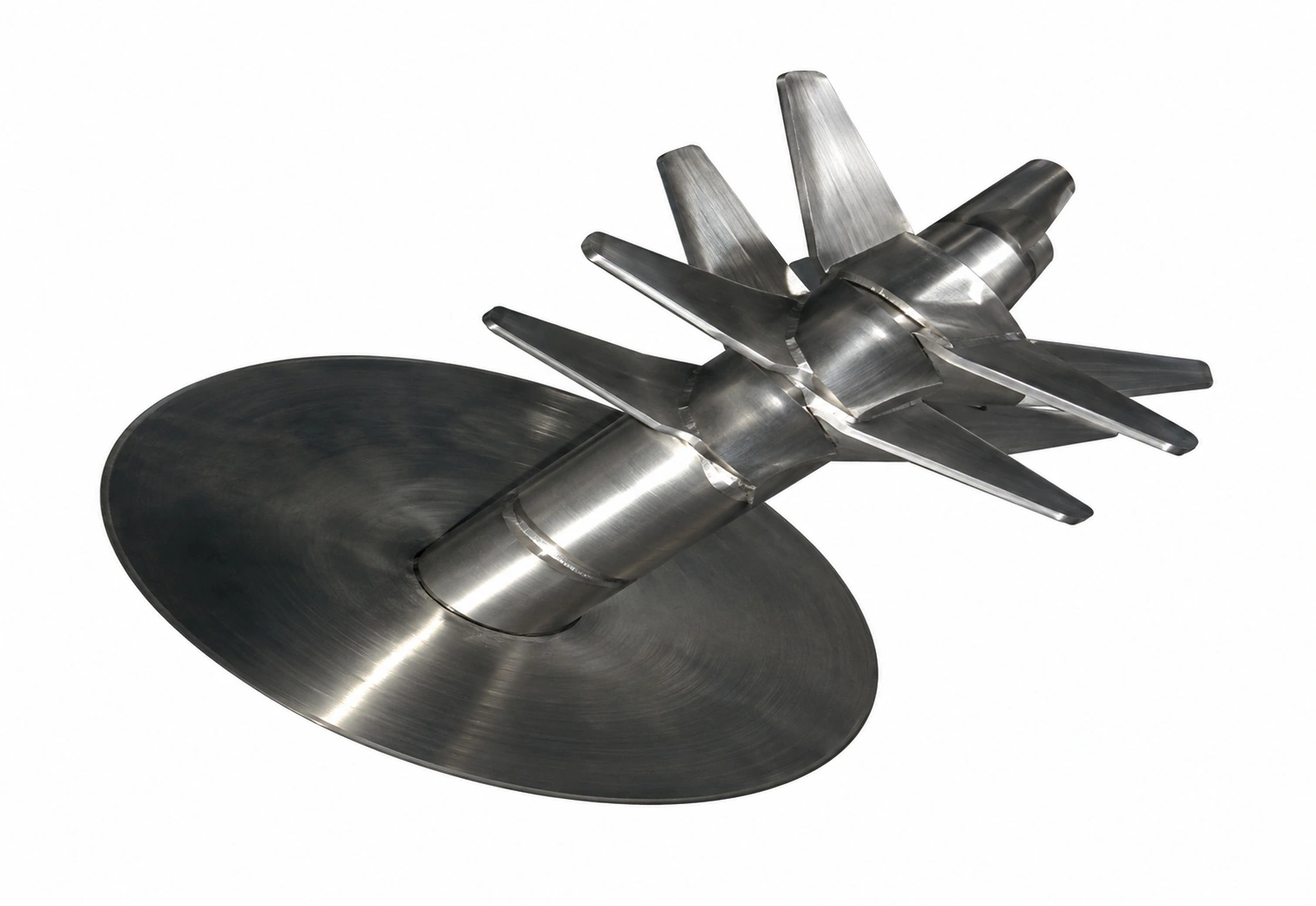
A liquid pipe passes through the hollow main shaft to a rotating atomizing nozzle for controlled liquid addition.
Ribbon circulation and cutter dispersion continue until the required blend uniformity is achieved.
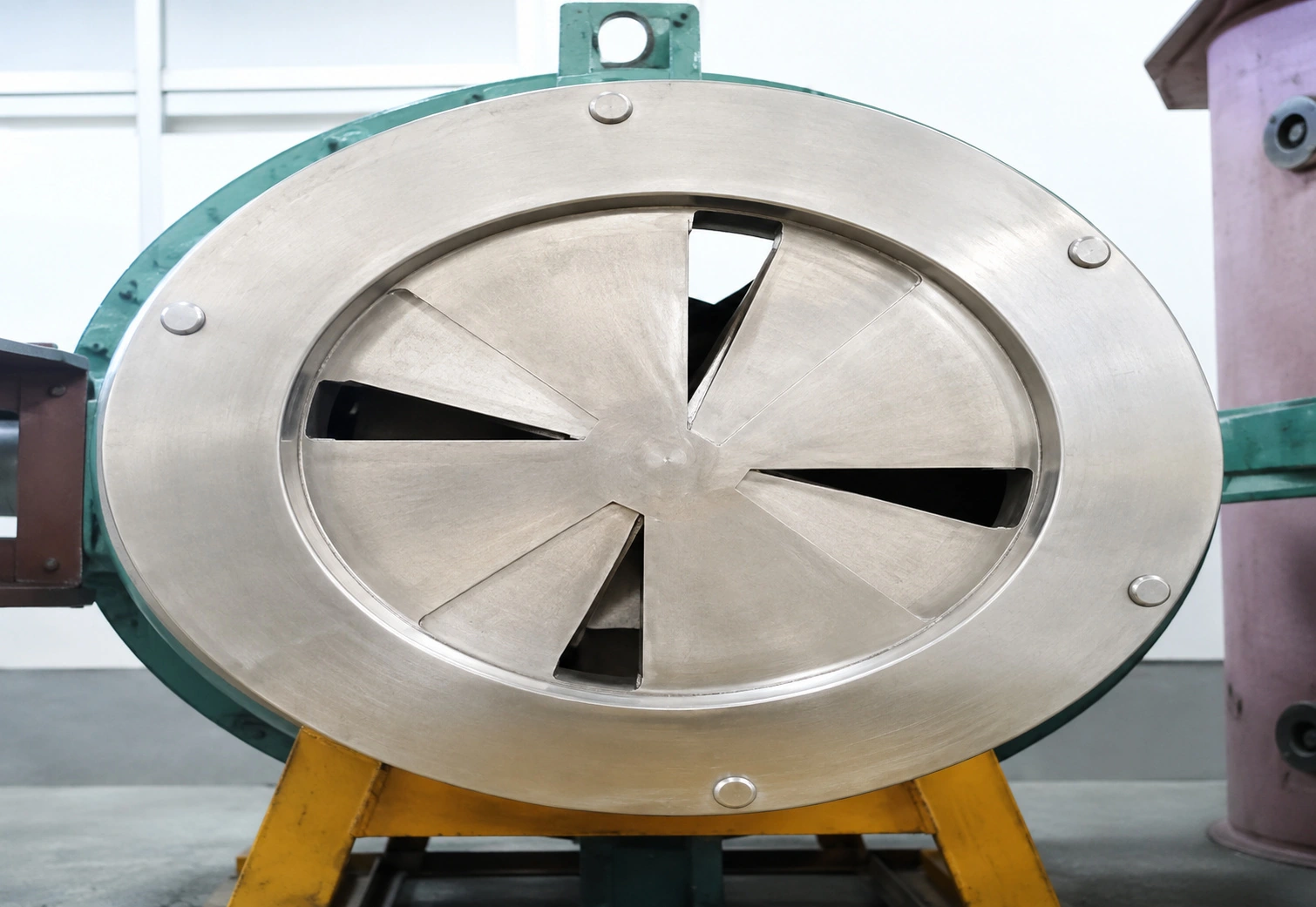
The finished batch leaves through the pneumatic bottom outlet, helping shorten discharge time and minimize retained material.
Performance Highlights
Final performance remains dependent on feed properties and engineering confirmation.
The ribbon provides primary circulation while the high-speed cutters disperse lumps and agglomerates.
Designed for particularly fine powders, granular additions, and fluid or semi-fluid materials such as paint formulations.
The two mixing actions promote thorough contact and consistent distribution throughout the batch.
Efficient ribbon circulation supports the mixing duty with comparatively low power demand.
Controlled bulk circulation helps limit unnecessary particle breakage.
A pneumatic outlet at the vessel bottom provides rapid emptying with reduced product hold-up.
A large quick-opening side door improves access to the chamber for cleaning, inspection and maintenance.
Pressure, vacuum blending, reaction and bonding duties can be engineered for the selected process.
System Configuration
Select options for the material and process. Availability and final scope are confirmed in the equipment specification.
The chamber houses the primary ribbon and supports efficient batch circulation.
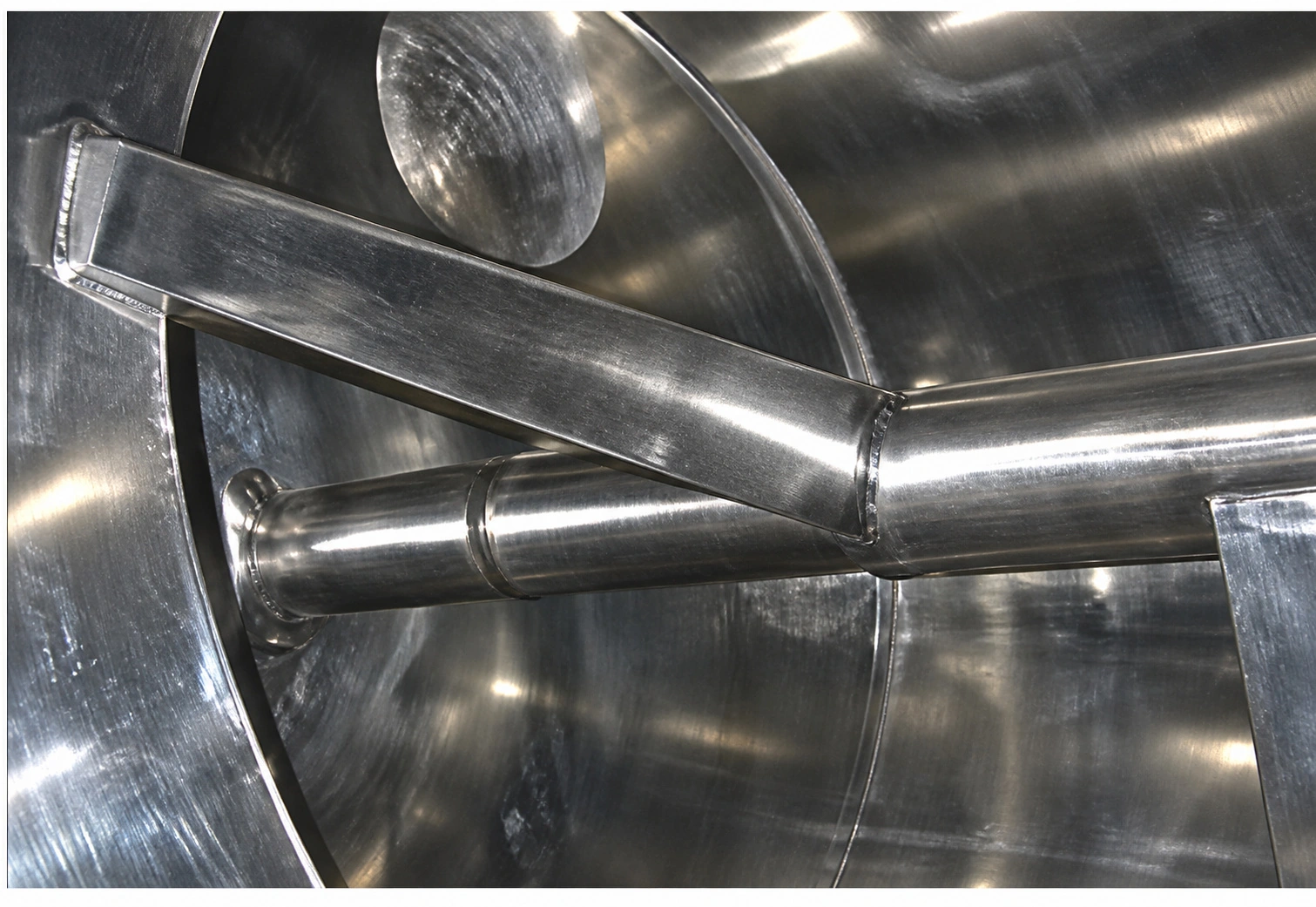
The central ribbon performs the main mixing action and circulates material throughout the working volume.
Direct-driven cutters assist mixing by cutting and dispersing agglomerated or caked material.
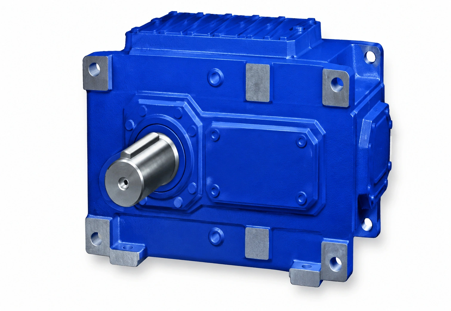
A motor directly coupled to a gear reducer drives the main ribbon; the feed opening is also arranged at the top.
The bottom-mounted pneumatic discharge enables fast emptying and helps reduce residual material.
Internal sprays assist cleaning of contact surfaces. The cleaning procedure is selected for the material residue.
Water cooling or steam/thermal-oil heating jackets can be specified for the process.
A spray line through the hollow shaft connects to a rotary union; atomizing nozzles rotate with the shaft for formulations requiring liquid addition.
Structure & Options

Selection Support
Share the following formulation, batch and process information for an efficient preliminary review.