
Chemical processing
Powdered chemicals, additives, pigments and formulated dry blends.
Industrial Mixers
Also known as a gravity-free mixer, this high-precision batch mixer uses counter-rotating paddle shafts to create rapid axial, radial and cross-flow circulation for uniform, low-energy mixing with limited particle degradation. Designed and manufactured for chemical processing and dry-mortar production. Review the working principle, performance features and available configuration details below when specifying your industrial project.
Product Essentials
Select a topic from the directory. The content stays in one focused workspace for faster comparison.
Product Overview
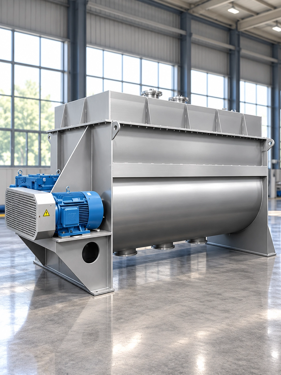
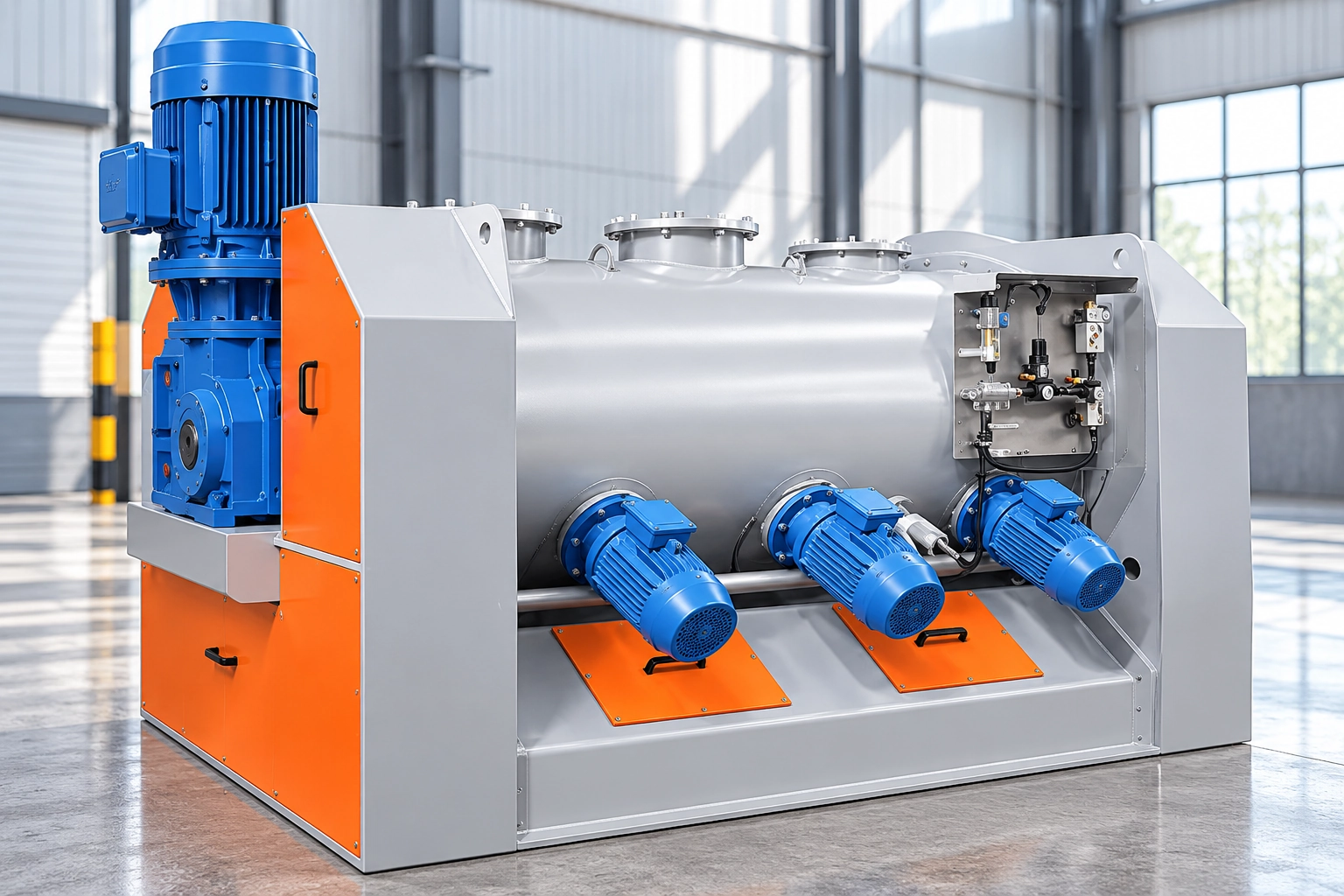
The twin-shaft paddle mixer, also known as a gravity-free mixer, combines a horizontal chamber, drive system and two counter-rotating shafts fitted with staggered paddles. Optional high-speed breaker bars can be added for materials that tend to agglomerate.
During operation, the paddles lift and throw the batch in multiple directions. Material circulates axially and radially, and the crossing trajectories briefly create a near-weightless state that promotes rapid, uniform mixing despite differences in density, particle size or component ratio.
Typical applications include chemical, dry-mortar, agrochemical, ceramic, food, feed and battery-material production.
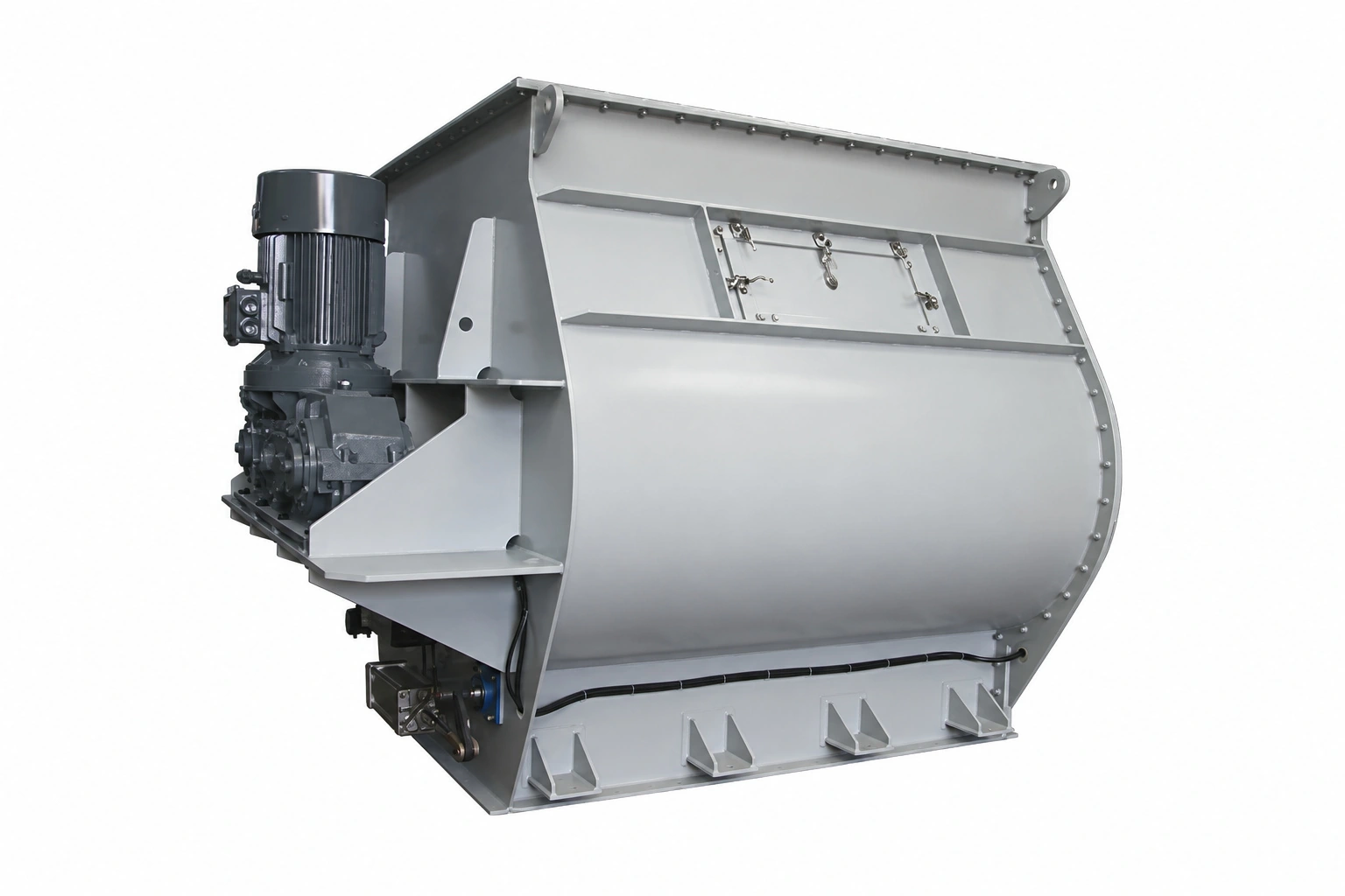
Typical Technical Data
Listed values apply to the identified configuration. Confirm material conditions, utilities and optional equipment before selection.
| Parameter | Reference value |
|---|---|
| Equipment type | Twin-shaft paddle batch mixer |
| Also known as | Gravity-free mixer |
| Mixing chamber | Horizontal mixing chamber |
| Mixing tool | Two counter-rotating shafts with staggered paddles |
| Suitable feed combinations | Powder + powder / granule + powder / granule + granule / powder + a small amount of liquid |
| Reference mixing uniformity | CV ≤ 3% for suitable, validated applications |
| Reference component ratio | Approximately 1:1,000 to 1:10,000 for suitable, validated applications |
| Optional breaker-bar speed | > 1,000 rpm |
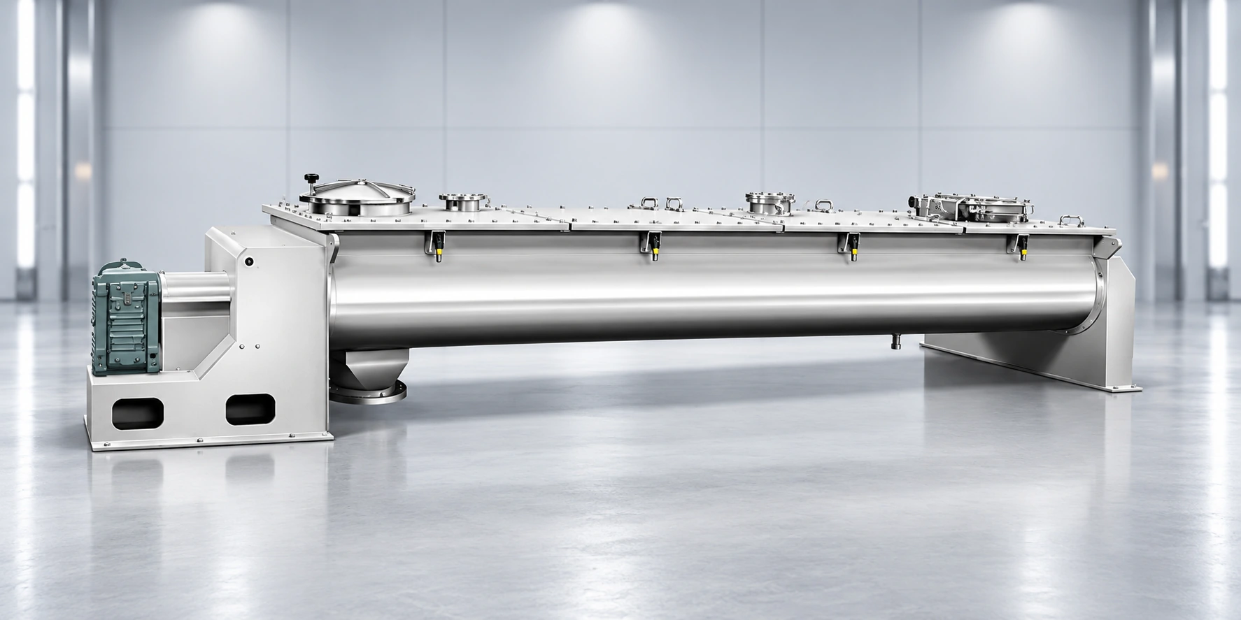
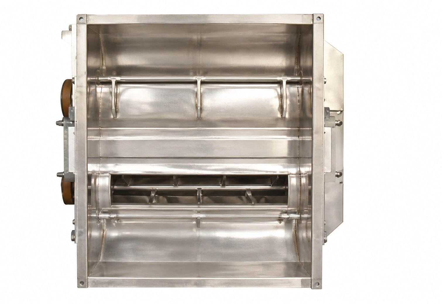
| Discharge options | Large-opening door / small-opening door |
| Reference maximum full volume | Up to 20 m³ |
| Large-machine drive | Direct-coupled gear reducer for models above 6 m³ |
| Optional cleaning design | Pull-out shaft assembly for cleaning access |
Final equipment dimensions, utilities and performance must be confirmed before quotation.
Technical Specifications
Reference full volume, loading coefficient, drive power, overall dimensions and equipment weight for preliminary model comparison.
| Reference Model | Total volume (m³) | Loading coefficient | Motor power (kW) | Overall dimensions L×W×H (mm) | Weight (kg) |
|---|---|---|---|---|---|
| WZ-0.05 | 0.05 | 0.4-0.6 | 1.5 | 1290×660×837 | 230 |
| WZ-0.2 | 0.2 | 0.4-0.6 | 4 | 1124×1110×720 | 260 |
| WZ-0.4 | 0.4 | 0.4-0.6 | 4 | 1400×1250×1030 | 450 |
| WZ-0.5 | 0.5 | 0.4-0.6 | 7.5 | 1450×1500×950 | 800 |
| WZ-1 | 1 | 0.4-0.6 | 11 | 1800×1800×1350 | 1150 |
| WZ-1.5 | 1.5 | 0.4-0.6 | 15 | 1850×1950×1180 | 1500 |
| WZ-2 | 2 | 0.4-0.6 | 18.5 | 2200×2400×1600 | 2800 |
| WZ-2.5 | 2.5 | 0.4-0.6 | 22 | 2300×2300×1620 | 4200 |
| WZ-4 | 4 | 0.4-0.6 | 22 | 2680×2400×1850 | 4500 |
| WZ-5 | 5 | 0.4-0.6 | 37 | 2950×3050×2040 | 6000 |
| WZ-6 | 6 | 0.4-0.6 | 45 | 3050×3250×2100 | 7000 |
| WZ-10 | 10 | 0.4-0.6 | 55 | 3550×3150×2400 | 8000 |
| WZ-12 | 12 | 0.4-0.6 | 55 | 4695×3180×2500 | 10500 |
| WZ-15 | 15 | 0.4-0.6 | 55 | 4180×3960×2600 | 10000 |
| WZ-20 | 20 | 0.4-0.6 | 75 | 5700×3700×2500 | 13000 |
Reference data is intended for preliminary selection. Confirm final dimensions, weight, motor configuration and process performance before quotation.
Applications
Applications include chemical processing and dry-mortar production. Confirm material properties and process conditions before selecting the equipment configuration.
Powdered chemicals, additives, pigments and formulated dry blends.
Dry mortar, construction compounds and mineral powder formulations.
Pesticide powders, additives and related formulated products.
Ceramic powders and multi-component mineral blends.
Food powders, ingredients, premixes and nutritional formulations.
Animal-feed premixes, additives and other dry feed formulations.
Battery powders and functional blends requiring controlled component distribution.
Working Principle
The process route is selected around the material and product targets.
Powder, granules, blended solids or powder with a small liquid addition is charged into the horizontal mixing chamber.
The two paddle shafts rotate in opposite directions to mobilize the complete batch.
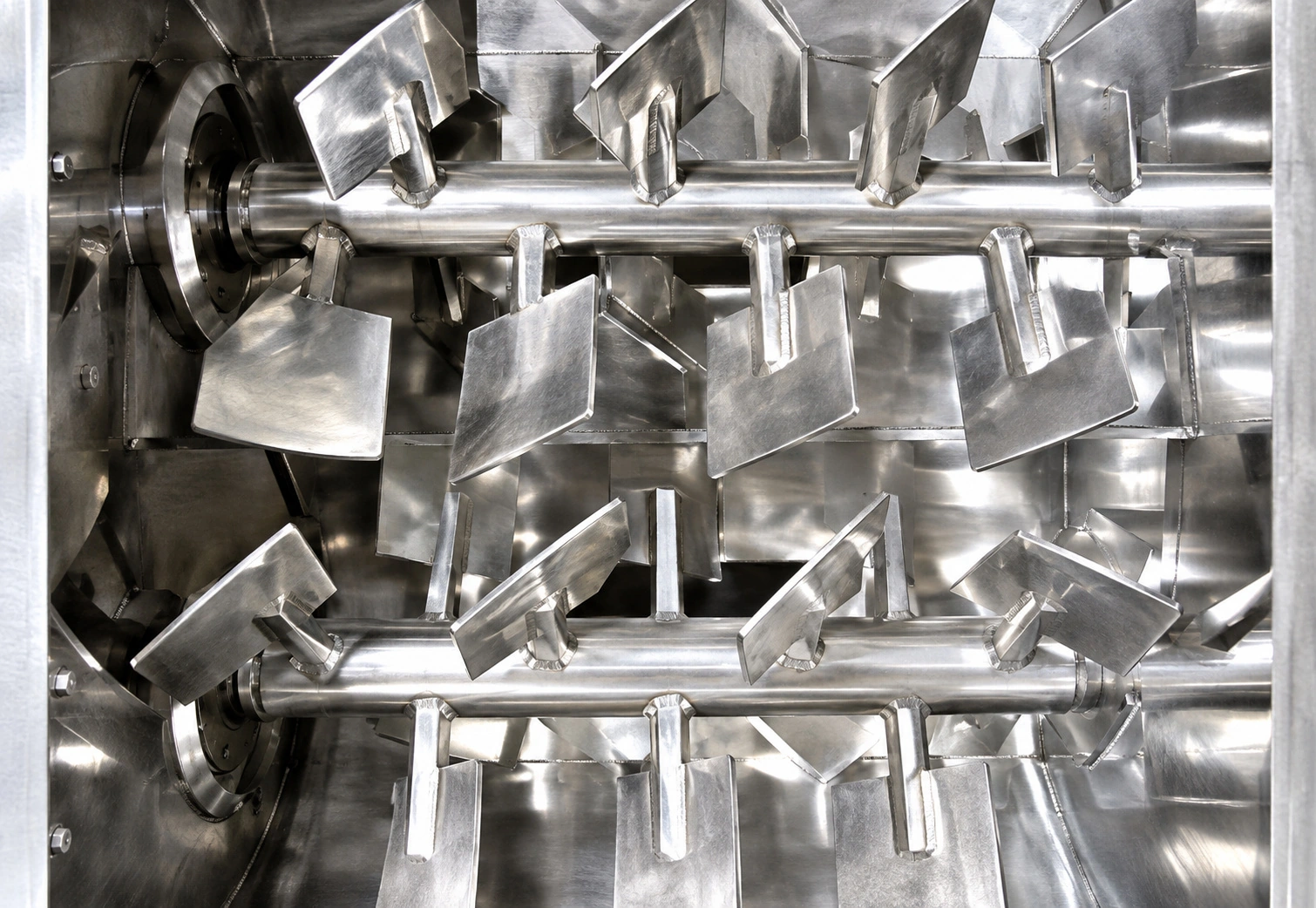
Angled, staggered paddles lift and project material into the upper portion of the chamber.
The paddle geometry drives simultaneous longitudinal, transverse and radial movement.
Repeated airborne crossing, falling and recirculation rapidly distribute major and minor ingredients.
Once the validated mixing endpoint is reached, the batch is released through the selected bottom discharge door.
Performance Highlights
Final performance remains dependent on feed properties and engineering confirmation.
High-speed paddle movement repeatedly lifts and crosses the batch, creating a near-weightless mixing zone for rapid component distribution.
For suitable, validated materials and operating conditions, the source specifies a coefficient of variation of CV ≤ 3%.
Suitable formulations can be blended at component ratios from approximately 1:1,000 to 1:10,000, subject to process validation.
Suitable combinations include powder + powder, granule + powder, granule + granule and powder + a small amount of liquid.
Rapid bulk circulation and short batch cycles support efficient power utilization.
Controlled paddle action helps limit unnecessary particle breakage in friable granular products.
Simultaneous axial, radial and cross-flow motion accelerates redistribution throughout the chamber.
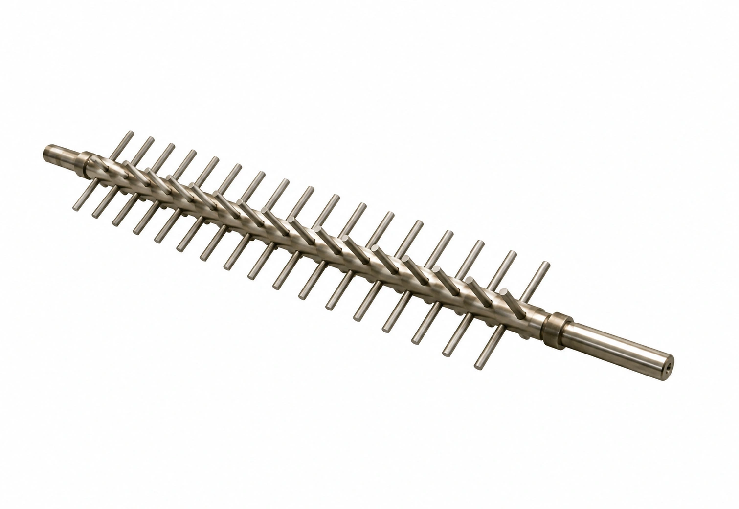
Triangular-tooth breaker bars can operate above 1,000 rpm to deagglomerate lumps inside the near-weightless zone.
Optional pull-out construction improves access to the vessel, paddles and internal surfaces for cleaning.
System Configuration
Select options for the material and process. Availability and final scope are confirmed in the equipment specification.
Two shafts with staggered, angled paddles create the axial, radial and cross-flow motion required for rapid blending.
Locally worn blade sections can be replaced individually, reducing wear-part cost and maintenance time.
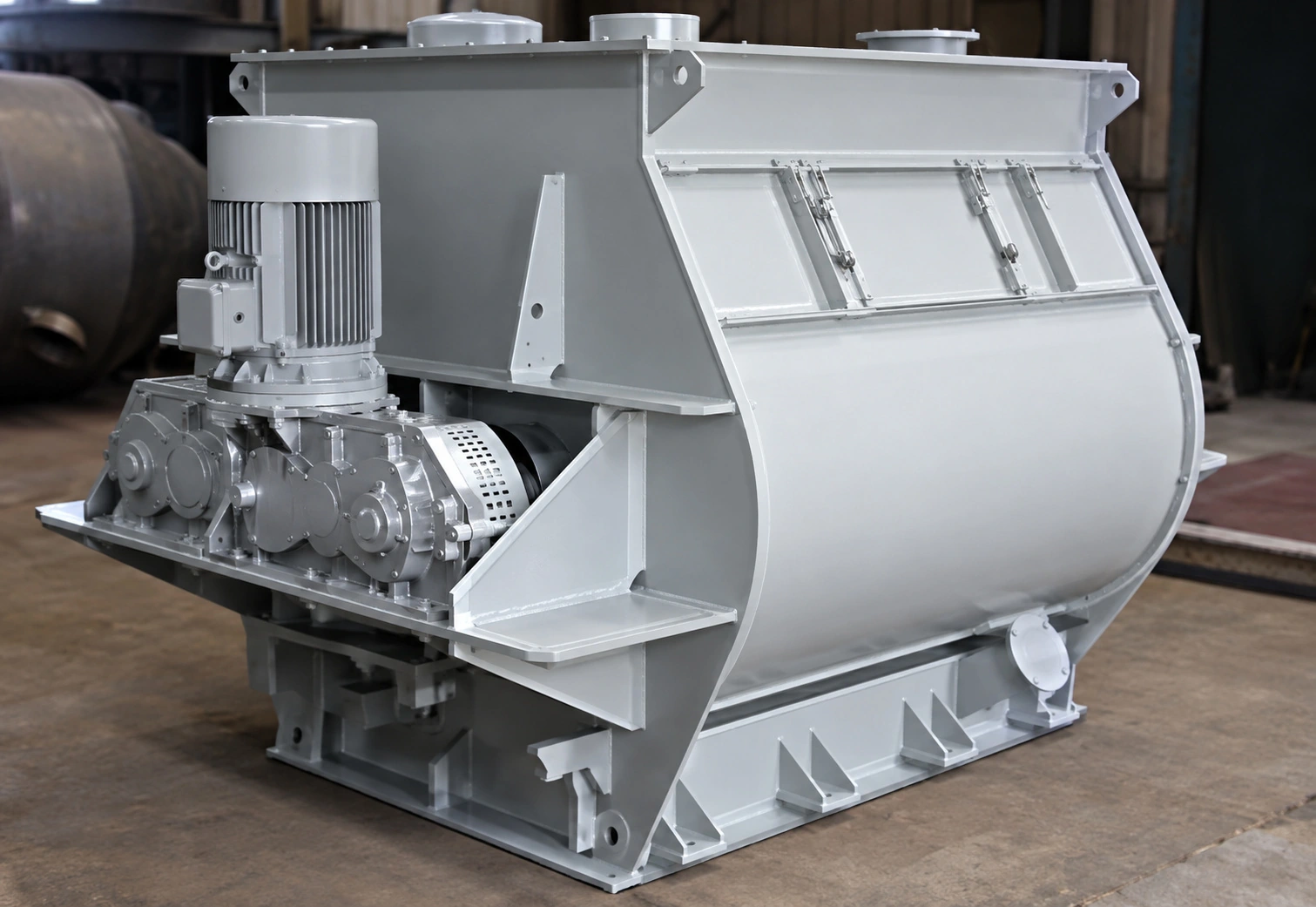
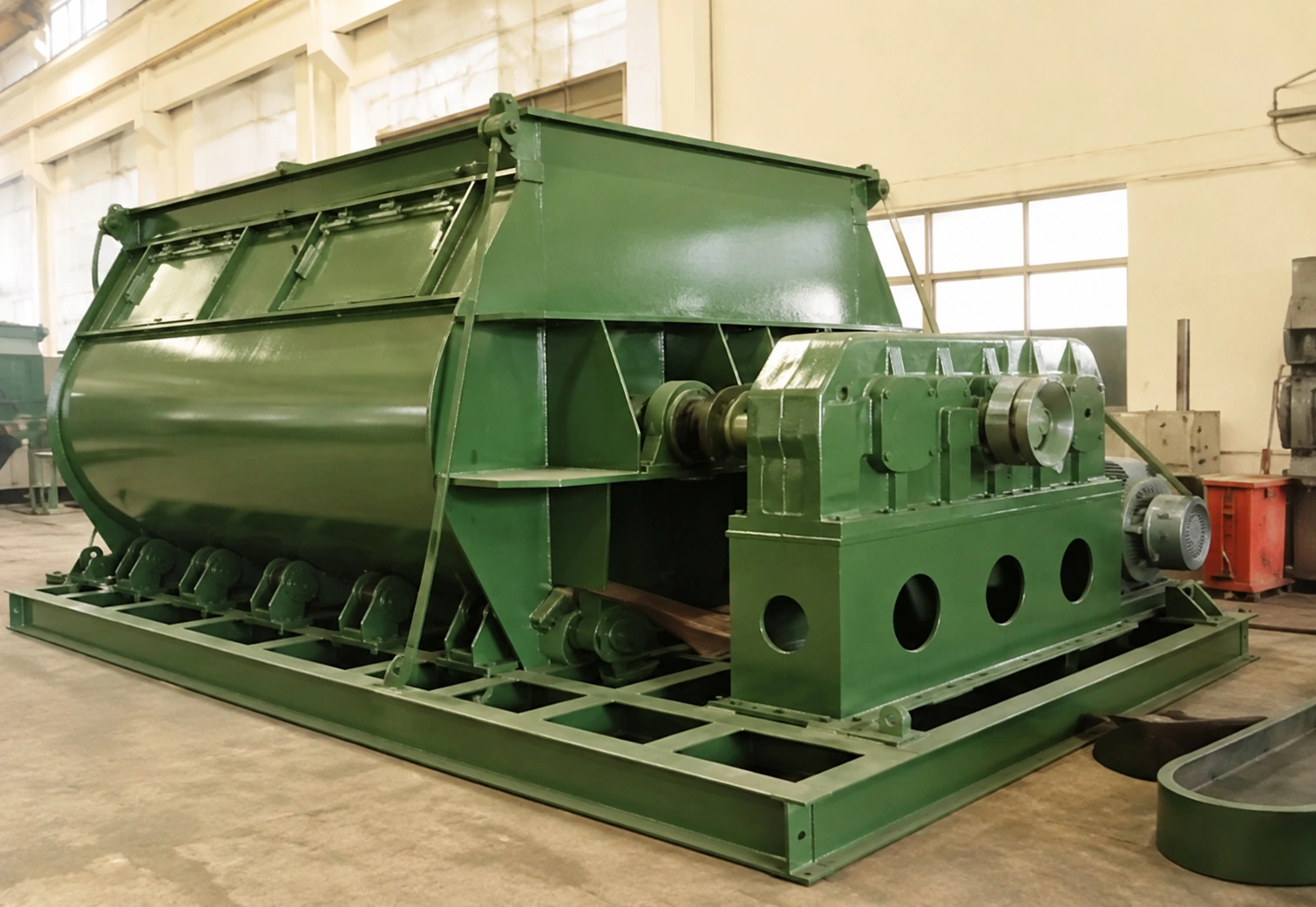
Models above 6 m³ use a direct-coupled gear reducer to increase available torque and reduce transmission maintenance.
The series can be engineered with a full vessel volume of up to 20 m³, using drive and base structures adapted for the larger scale.
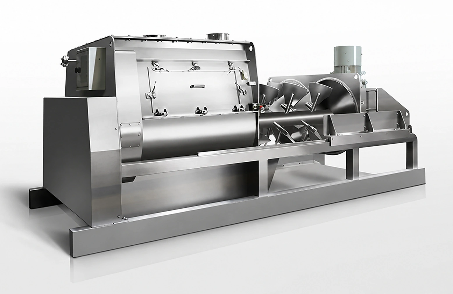
The side cover separates from the vessel to provide access to paddles and contact surfaces for cleaning, inspection and wear-part replacement.
An optional breaker disperses agglomerates. Speed and processing intensity are selected through material evaluation.
Large or small discharge openings are selected for downstream handling. A pneumatic flap matching the vessel contour helps limit material retention.
Equipment Details
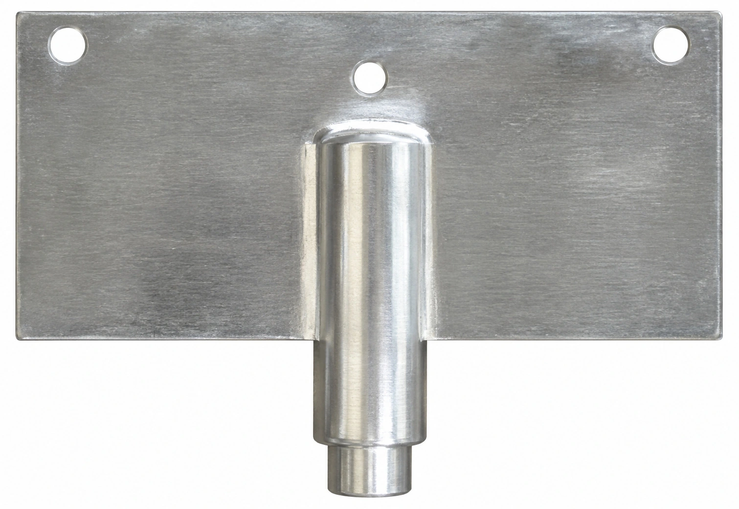
Images below illustrate the corresponding mechanical details and available configurations.
Selection Support
Share the following formulation, batch and process information for an efficient preliminary review.