
Chemical processing
Powdered chemicals, additives, pigments and other formulated dry blends.
Industrial Mixers
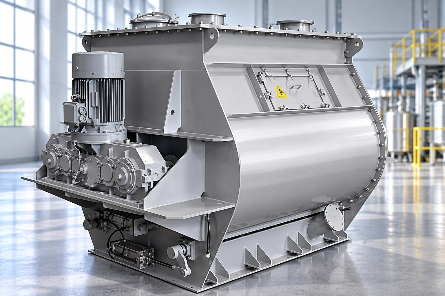
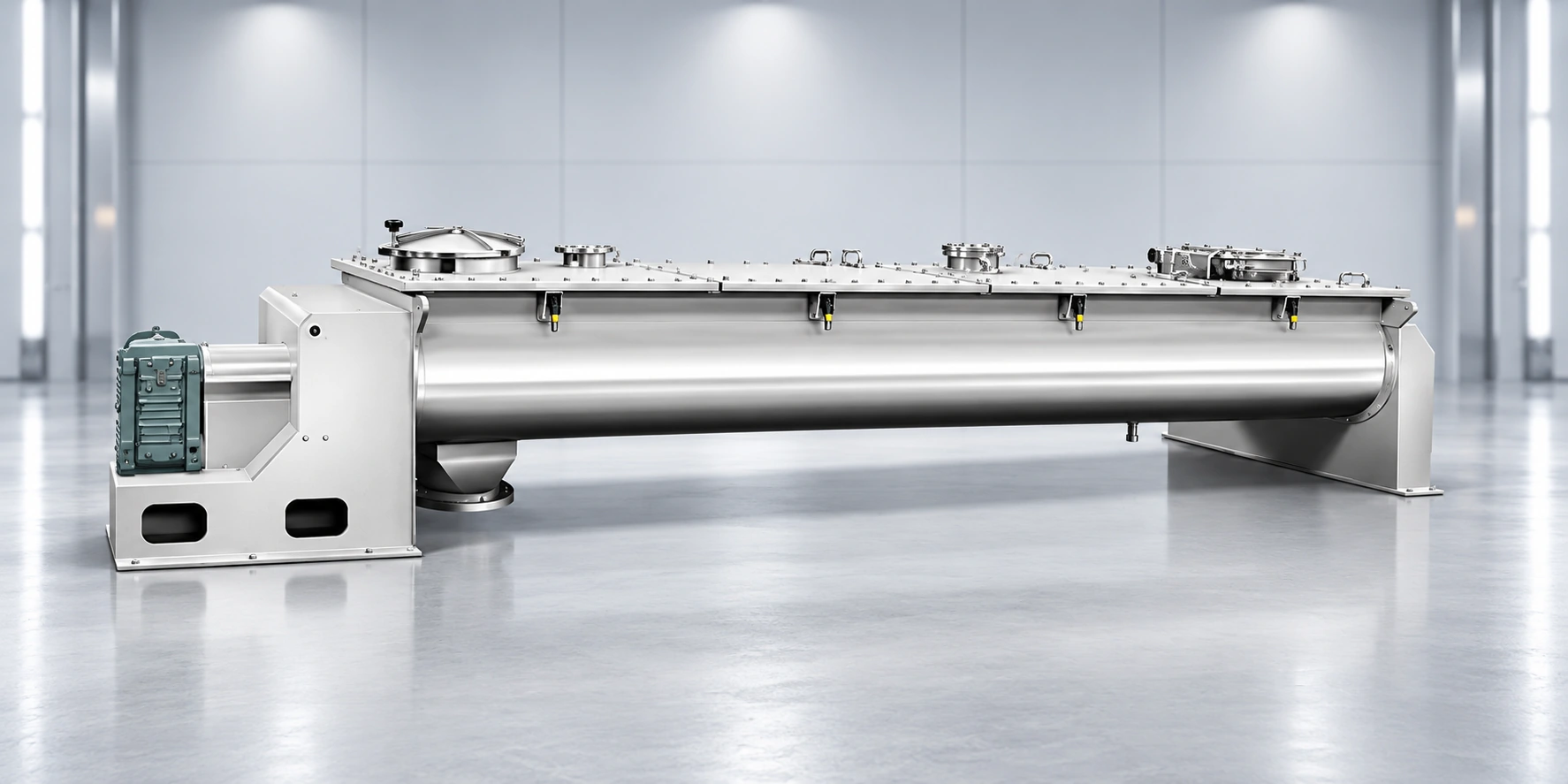
A horizontal batch blender with a U-shaped trough and counter-flow double-ribbon agitator, engineered for uniform mixing with low energy demand, gentle product handling and optional automated cleaning. Designed and manufactured for chemical processing and pharmaceutical production. Review the working principle, performance features and available configuration details below when specifying your industrial project.
Product Essentials
Select a topic from the directory. The content stays in one focused workspace for faster comparison.
Product Overview
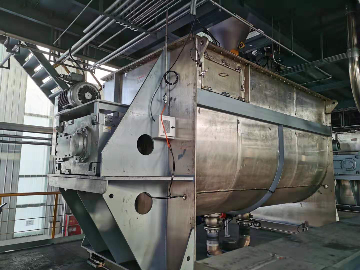
The horizontal ribbon blender combines an integral-welded U-shaped trough, a counter-flow double-ribbon agitator and a robust drive system for batch mixing of powders, granules and powder with a small liquid addition. GMP-oriented construction can be provided when required.
During operation, the outer ribbon moves material from both ends toward the center, while the inner ribbon returns it from the center toward both ends. This opposing transport creates continuous circulation, turnover and convection for uniform blending within a short cycle.
Typical applications include chemical, pharmaceutical, food, feed, plastics and building-material production. Heating, cooling, positive-pressure, vacuum and CIP versions are available as project-specific options.
Typical Technical Data
Listed values apply to the identified configuration. Confirm material conditions, utilities and optional equipment before selection.
| Parameter | Reference value |
|---|---|
| Equipment type | Horizontal batch ribbon blender |
| Mixing chamber | Integral-welded horizontal U-shaped trough |
| Standard mixing tool | Double-layer inner and outer ribbon |
| Alternative mixing tools | Paddle agitator and optional high-speed chopper |
| Suitable feed combinations | Powder + powder / granule + powder / powder + a small amount of liquid |
| Reference component ratio | Approximately 1:1,000 to 1:10,000 for suitable, validated applications |
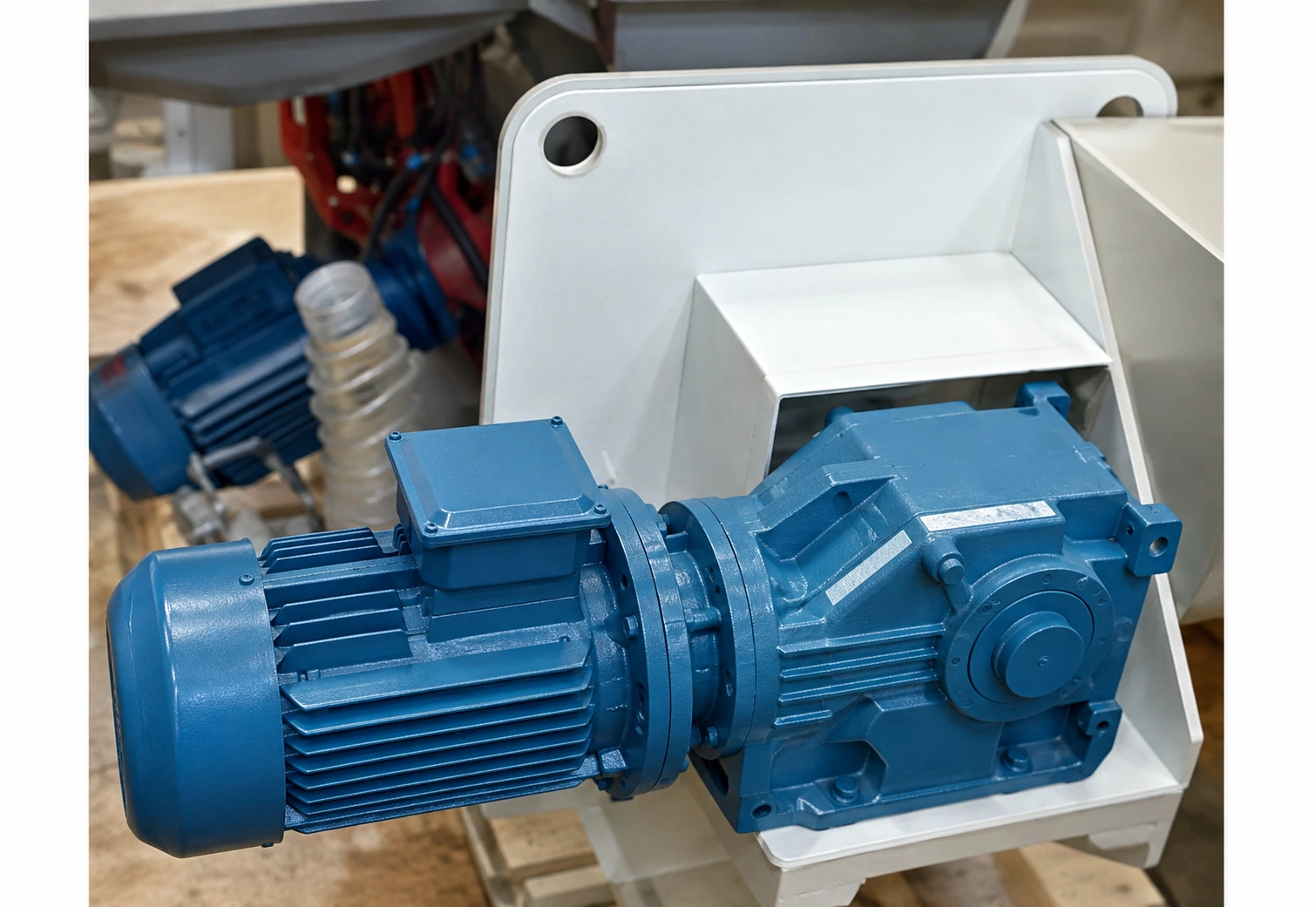
| Standard drive | Direct-coupled gear reducer |
| Large-machine drive option | Gear reducer with belt transmission |
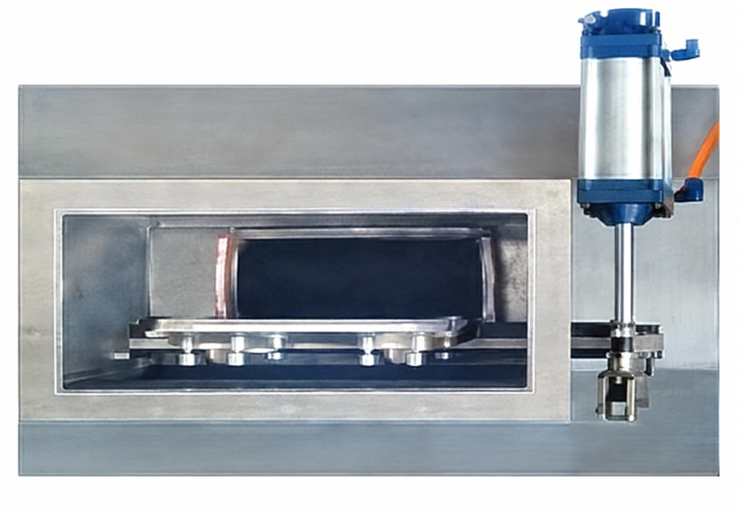
| Standard discharge | Pneumatic flush-mounted flap valve |
| Optional process versions | Heating / cooling / positive pressure / vacuum |
| Optional hygiene package | GMP-oriented construction and CIP cleaning |
Final equipment dimensions, utilities and performance must be confirmed before quotation.
Fourteen sizes cover 0.1–15 m³ total volume. Working load depends on bulk density and the loading coefficient.
| Reference Model | Total Volume (m³) | Loading Coefficient | Motor Power (kW) | Overall Dimensions (mm) | Weight (kg) |
|---|---|---|---|---|---|
| WLDH-0.1 | 0.1 | 0.4–0.6 | 3 | 1190×740×770 | 330 |
| WLDH-0.3 | 0.3 | 0.4–0.6 | 4 | 2030×630×980 | 720 |
| WLDH-0.5 | 0.5 | 0.4–0.6 | 7.5 | 2320×730×1130 | 980 |
| WLDH-1 | 1 | 0.4–0.6 | 11 | 2800×920×1320 | 1700 |
| WLDH-1.5 | 1.5 | 0.4–0.6 | 11 | 3180×1020×1550 | 1800 |
| WLDH-2 | 2 | 0.4–0.6 | 15 | 3310×1120×1640 | 2100 |
| WLDH-3 | 3 | 0.4–0.6 | 18.5 | 3750×1290×1820 | 3000 |
| WLDH-4 | 4 | 0.4–0.6 | 22 | 4220×1400×1990 | 3980 |
| WLDH-5 | 5 | 0.4–0.6 | 22 | 4220×1500×2100 | 4620 |
| WLDH-6 | 6 | 0.4–0.6 | 30 | 4700×1610×2260 | 6180 |
| WLDH-8 | 8 | 0.4–0.6 | 37 | 4420×2150×2470 | 8200 |
| WLDH-10 | 10 | 0.4–0.6 | 45 | 5520×2960×2720 | 8920 |
| WLDH-12 | 12 | 0.4–0.6 | 45 | 5720×3010×2840 | 9520 |
| WLDH-15 | 15 | 0.4–0.6 | 55 | 5840×3540×2940 | 9950 |
Reference values support preliminary selection. Final dimensions, drive power and weight depend on the material and selected options.
Applications
Applications include chemical processing and pharmaceutical production. Confirm material properties and process conditions before selecting the equipment configuration.
Powdered chemicals, additives, pigments and other formulated dry blends.
Active or intermediate powder blends where the final design may be adapted to GMP requirements.
Food ingredients, seasonings, additives and nutritional powder blends.
Premixes, additives and other dry feed formulations.
Polymer additives, masterbatch ingredients and related powder or granule blends.
Dry construction compounds and formulated mineral powders.
Working Principle
The process route is selected around the material and product targets.
Powder, granules, or powder with a small liquid addition is charged into the horizontal U-shaped trough.
The inner and outer helical ribbons rotate as one assembly to mobilize the complete batch.
The outer ribbon conveys material inward while the inner ribbon returns material toward both ends.
Repeated axial movement, radial displacement and particle turnover distribute minor and major components through the batch.
Mixing continues for the validated cycle time until the specified blend uniformity is achieved.
The batch is discharged through the bottom valve, whose flush-mounted profile helps minimize residue and unmixed pockets.
Performance Highlights
Final performance remains dependent on feed properties and engineering confirmation.
Opposing inner- and outer-ribbon flows create continuous convection and distribute ingredients throughout the working volume.
For suitable materials and validated operating conditions, the source indicates effective mixing at component ratios from approximately 1:1,000 to 1:10,000.
Suitable duties include powder + powder, granule + powder and powder + a small amount of liquid.
Efficient bulk circulation reduces unnecessary resistance and supports economical batch operation.
The ribbon action limits excessive particle impact, helping reduce degradation of friable granules.
Simultaneous inward and outward transport accelerates material turnover and can shorten the time required to reach uniformity.
The horizontal U-shaped trough provides effective use of the available batch volume.
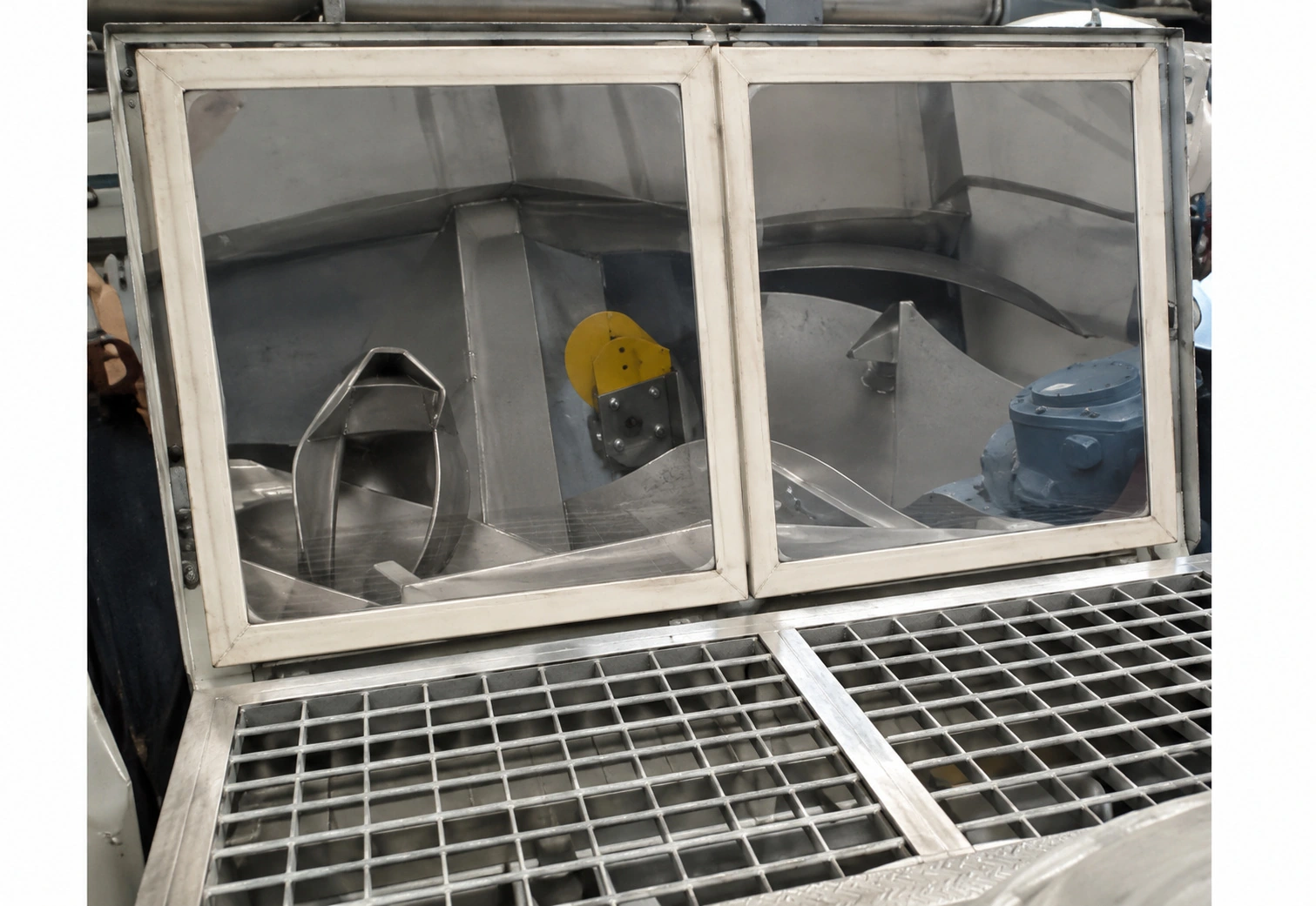
Arched, fully open, semi-open and fully enclosed covers are available for pressure, cleaning-access and containment requirements.
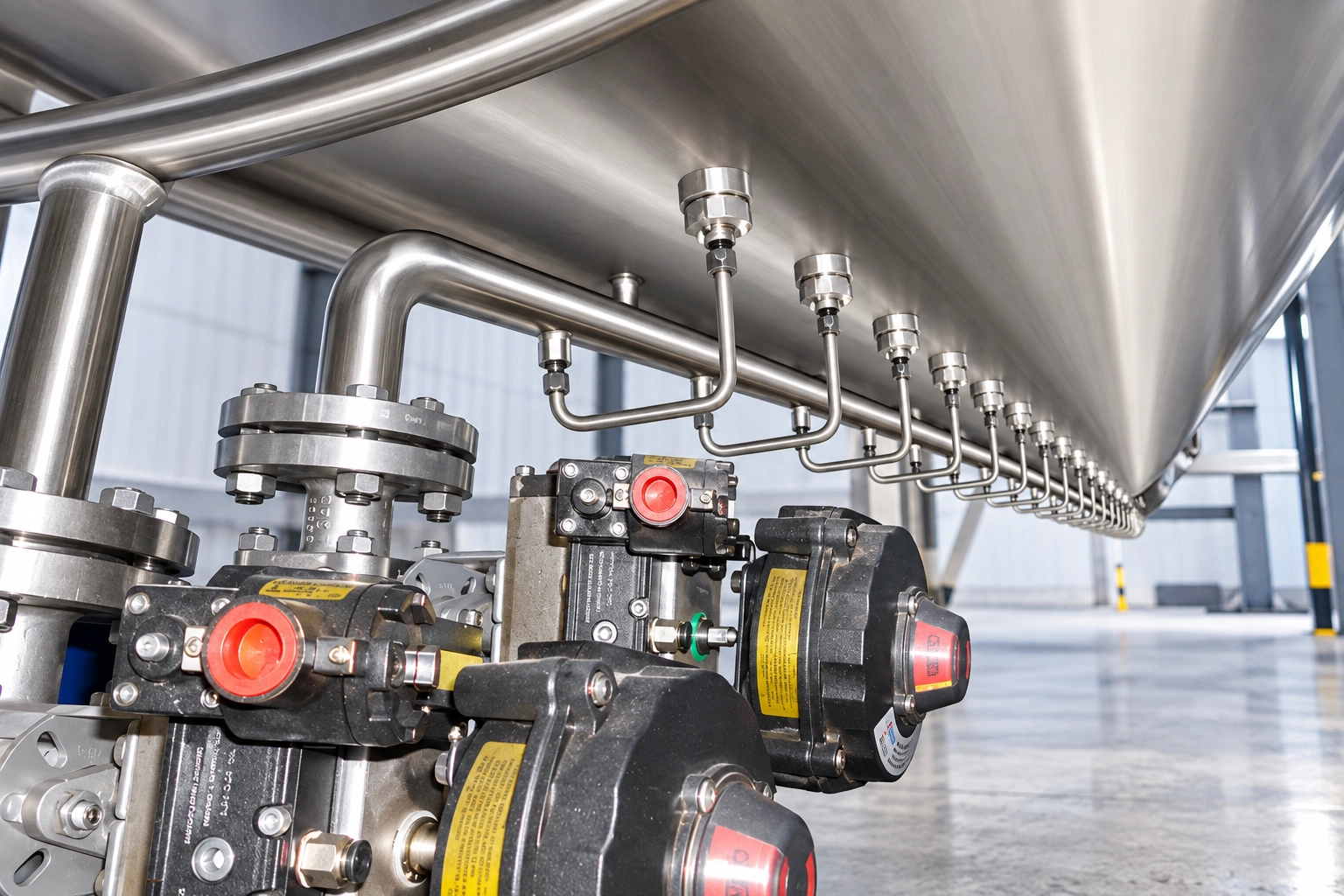
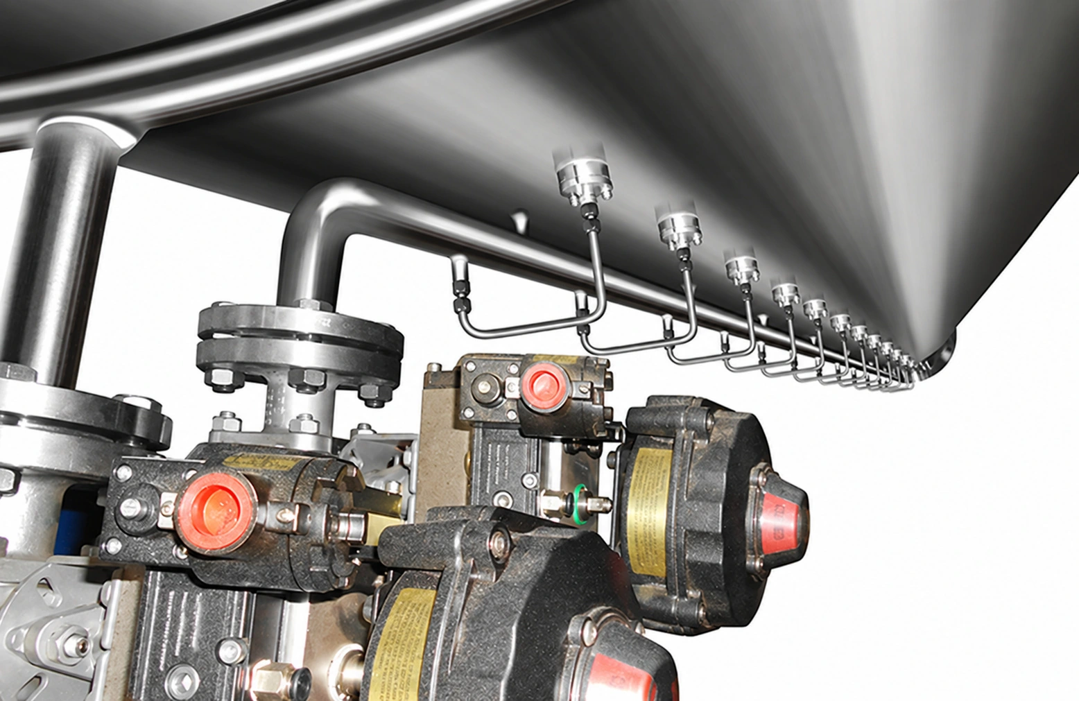
A CIP system can circulate heated cleaning solution through closed piping and internal spray devices to reduce residues and cross-contamination.
System Configuration
Select options for the material and process. Availability and final scope are confirmed in the equipment specification.
The trough and end plates are welded as one assembly to avoid product-holding gaps associated with bolted trough flanges.
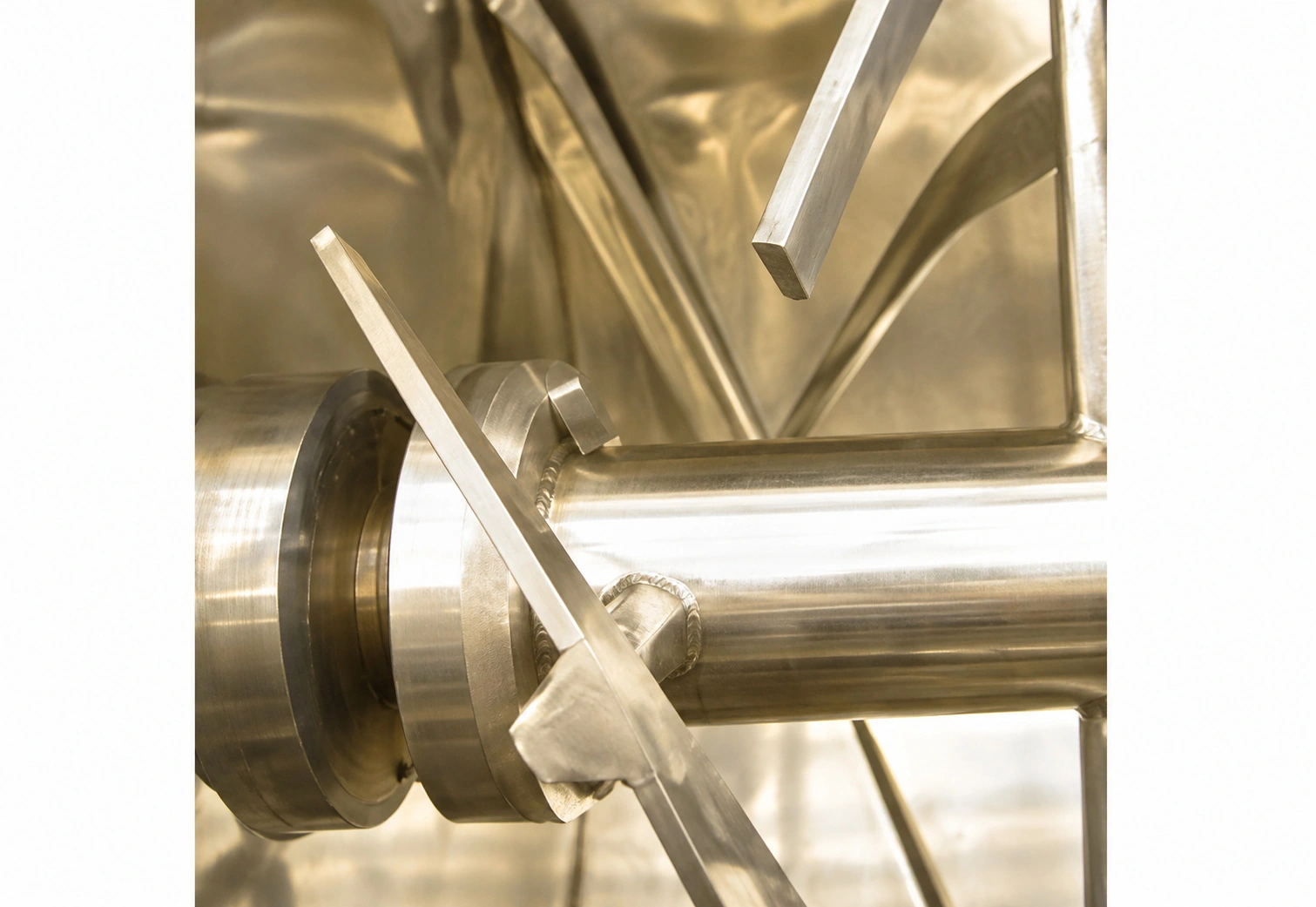
Counter-flow inner and outer ribbons generate rapid axial circulation and batch turnover.
Paddle elements or a high-speed chopper can be incorporated where the material and mixing objective require them.
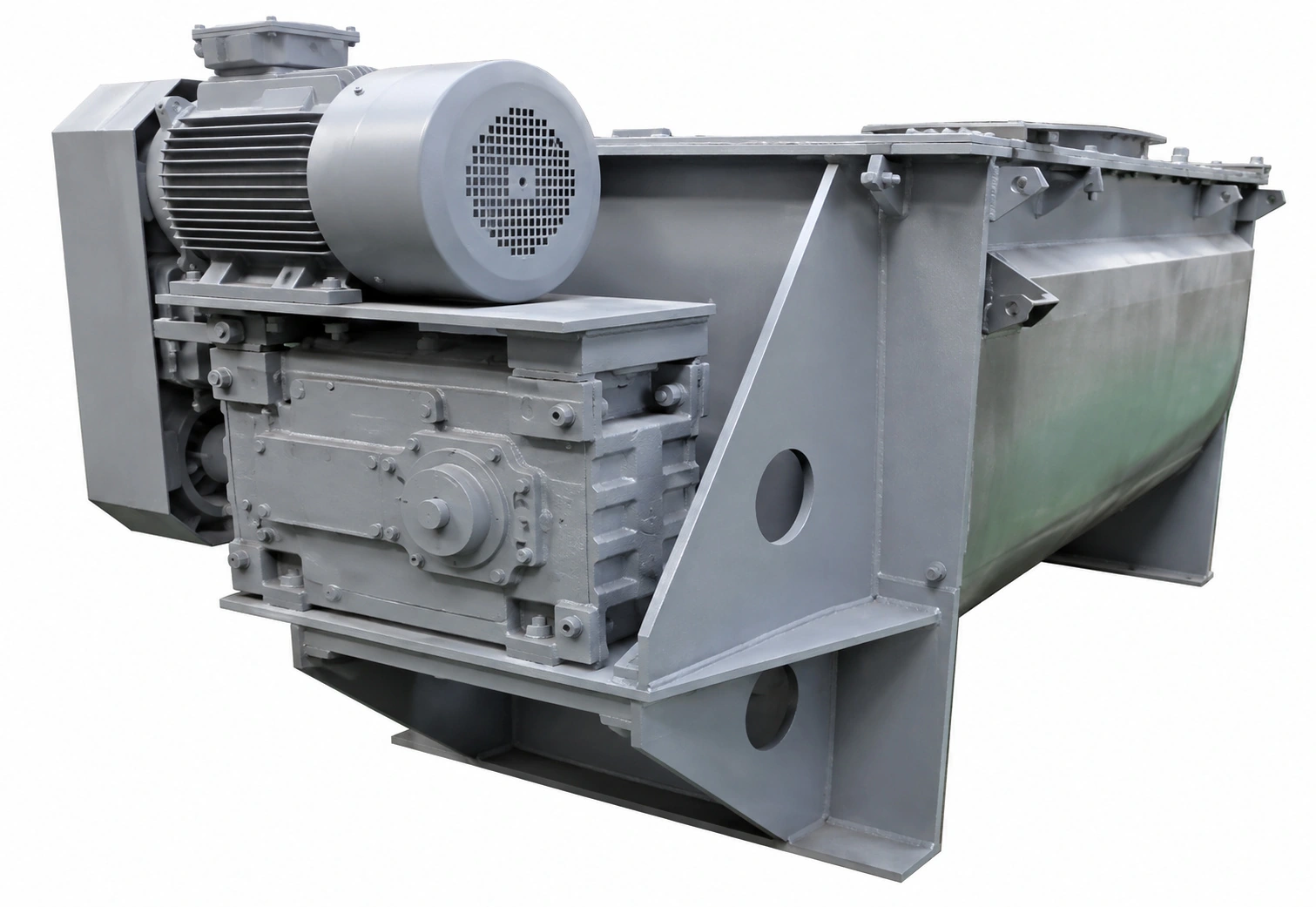
Standard machines use a gear reducer directly coupled to the shaft for high torque, reliability and low operating noise.
A gear reducer and belt transmission can be used on larger units and can provide additional protection to drive components during abnormal loads.
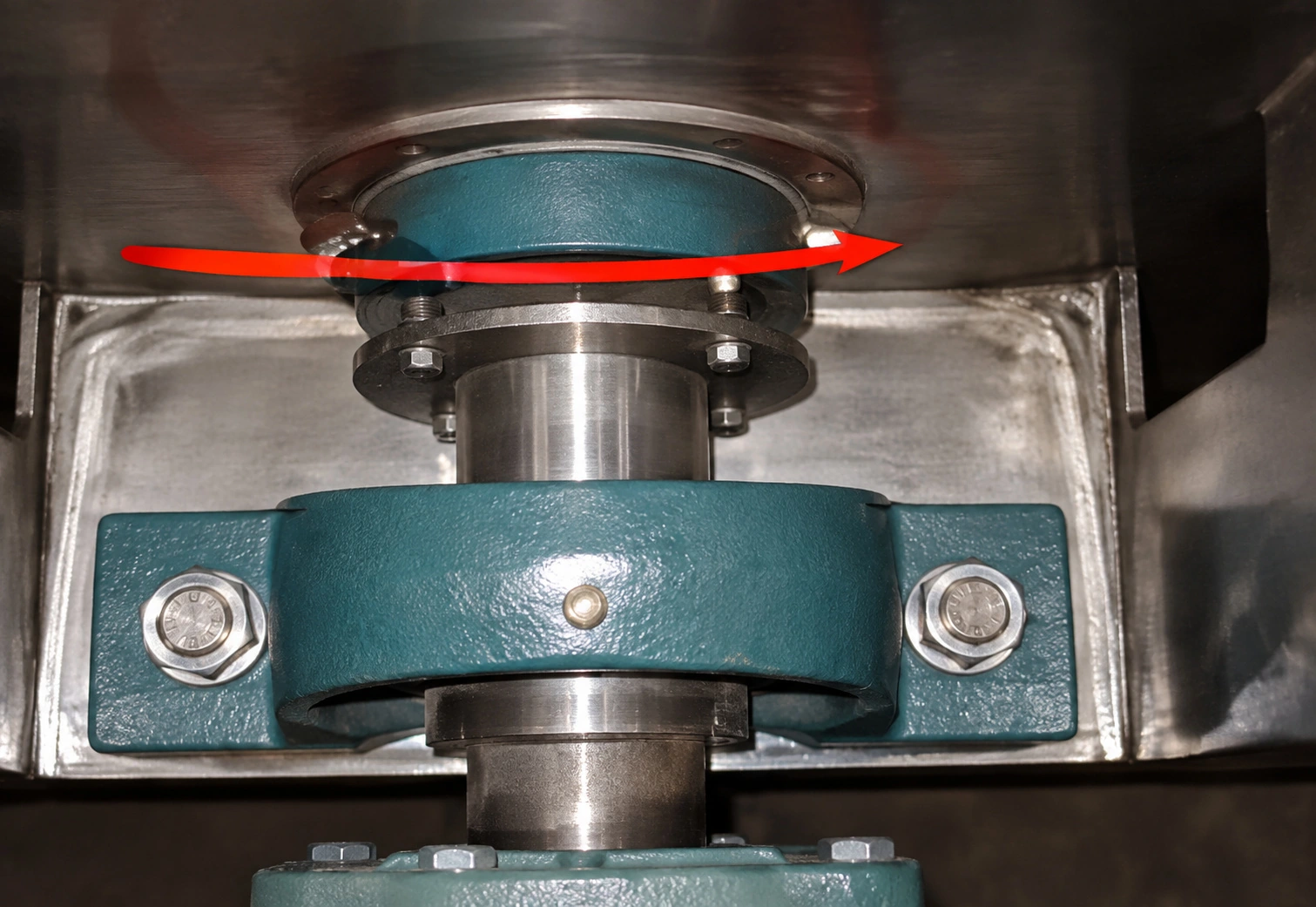
The ribbon shaft connects to the drive shaft by flange, allowing faster removal for maintenance or agitator replacement.
The curved valve face follows the trough profile to reduce accumulation and dead zones; edge-strip sealing supports repeated operation.
A balanced air seal combined with packing improves gas tightness and limits ultra-fine powder migration between the vessel and the surrounding area.
Heated, cooled, positive-pressure and vacuum designs can be engineered to suit project requirements.
Full-opening, half-opening or closed covers can be selected for cleaning and maintenance. Pressure-rated construction requires separate specification.
Internal spray devices clean product-contact surfaces. Cleaning media, spray coverage and drainage must be selected for the material.
Select water cooling or steam/thermal-oil heating to suit the material and temperature-control requirements.
Equipment Details
Images below illustrate the corresponding mechanical details and available configurations.
Selection Support
Share the following formulation, batch and process information for an efficient preliminary review.